
Robot joint module

A technology of robot joints and modules, which is applied in the field of robots, can solve the problems of chaotic wiring, heavy weight, and difficult maintenance of parts, and achieve the effect of convenient follow-up maintenance, simple and compact structure, and preventing chaotic wiring

Pending Publication Date: 2021-01-15
深圳市零差云控科技有限公司
View PDF0 Cites 6 Cited by
  • Summary
  • Abstract
  • Description
  • Claims
  • Application Information

AI Technical Summary

Problems solved by technology

[0003] In the robot joint module in the prior art, its structure is complex, and the corresponding read heads and driver circuits are distributed on different circuit boards, which leads to confusing wiring and difficult installation. At the same time, the entire joint needs multiple parts to assemble, and the obtained The joints are large in size, heavy in weight, and difficult to maintain due to too many parts, which greatly restricts the use of the robot

Method used


Image

  • Robot joint module
  • Robot joint module
  • Robot joint module

Examples


Embodiment Construction

[0022] Now in conjunction with the accompanying drawings, the preferred embodiments of the present invention will be described in detail.

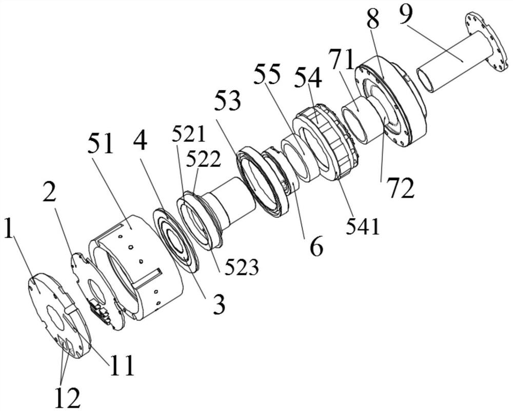
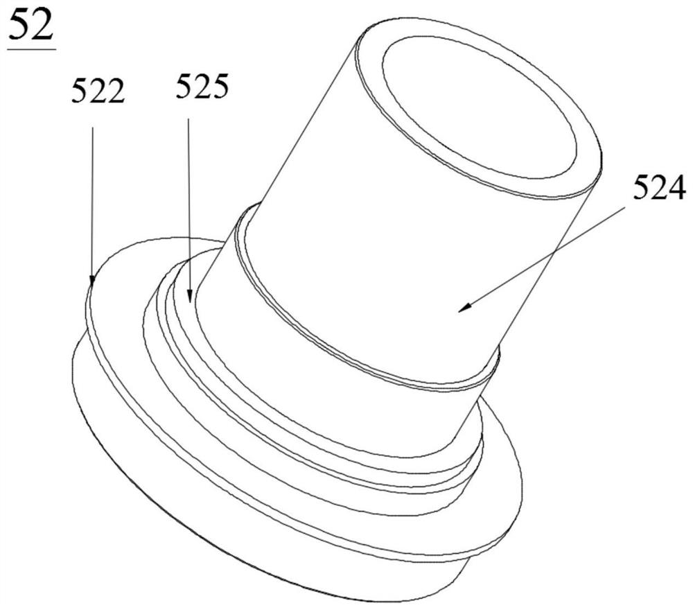
[0023] like Figure 1-5 As shown, the present invention provides a robot joint module, which includes a module end cover 1, a circuit board 2, an encoder code disc, a motor, a brake 6, a reducer 8 and a reducer output shaft 9, wherein the The encoder code disc includes the first code disc 3 of the encoder for measuring the rotation angle of the output shaft 9 of the reducer, and the second code disc 4 of the encoder for measuring the rotation angle of the motor, and the motor driver circuit is arranged on the circuit board 2 , motor input end read head circuit and reducer output end read head circuit, motor input end read head circuit, reducer output end read head circuit corresponding to encoder second code disc 4, encoder first code disc 3 position setting respectively. The first code disc 3 of the encoder is set to measure the rotation...


PUM


Abstract

The invention relates to the technical field of robots, in particular to a robot joint module. The robot joint module comprises a module end cover, a circuit board, an encoder coded disc, a motor, a brake, a speed reducer and a speed reducer output shaft which are arranged in sequence, wherein the encoder coded disc comprises an encoder first coded disc used for measuring the rotating angle of thespeed reducer output shaft and an encoder second coded disc used for measuring the rotating angle of the motor, a motor driver circuit, a motor input end read head circuit and a speed reducer outputend read head circuit are arranged on the circuit board, and the motor input end read head circuit and the speed reducer output end read head circuit are arranged corresponding to the encoder second coded disc and the encoder first coded disc respectively. According to the robot joint module, the motor input end read head circuit, the speed reducer output end read head motor and the motor driver circuit are arranged on the circuit board in a unified mode, wiring disorder of the joint module is prevented, integration of the joint module structure is facilitated, and it is guaranteed that the structure is simple and compact and follow-up maintenance is also facilitated.

Description

technical field [0001] The invention relates to the technical field of robots, in particular to a robot joint module. Background technique [0002] With the rapid development of industrial automation technology, robots, as an important industrial automation equipment, are getting more and more attention and are used more and more widely. In robot-related technologies, the control of moving parts such as robot joints is the most important and critical. [0003] In the robot joint module in the prior art, its structure is complex, and the corresponding read heads and driver circuits are distributed on different circuit boards, which leads to confusing wiring and difficult installation. At the same time, the entire joint needs multiple parts to assemble, and the obtained The joints are large in size, heavy in weight, and difficult to maintain due to too many parts, which greatly restricts the use of the robot as a whole. Contents of the invention [0004] The technical prob...

Claims


Application Information

Patent Timeline
Patent Type & Authority Applications(China)
IPC IPC(8): B25J17/00B25J9/08
CPCB25J17/00B25J9/08
Inventor 贾玺庆
Owner 深圳市零差云控科技有限公司
Learn More