
Joint space continuous point track transition method and device

A technology of joint space and point trajectory, which is applied in the direction of program control manipulators, manufacturing tools, manipulators, etc., can solve the problems of high time cost and energy consumption cost, and achieve the effect of reducing time cost, continuous speed, and reducing energy cost

Active Publication Date: 2021-01-15
合肥哈工图南智控机器人有限公司
View PDF5 Cites 10 Cited by
  • Summary
  • Abstract
  • Description
  • Claims
  • Application Information

AI Technical Summary

Problems solved by technology

[0004] The technical problem to be solved by the present invention lies in the high time cost and high energy consumption cost of joint space continuous point trajectory transition method

Method used


Image

  • Joint space continuous point track transition method and device
  • Joint space continuous point track transition method and device
  • Joint space continuous point track transition method and device

Examples


Embodiment 1

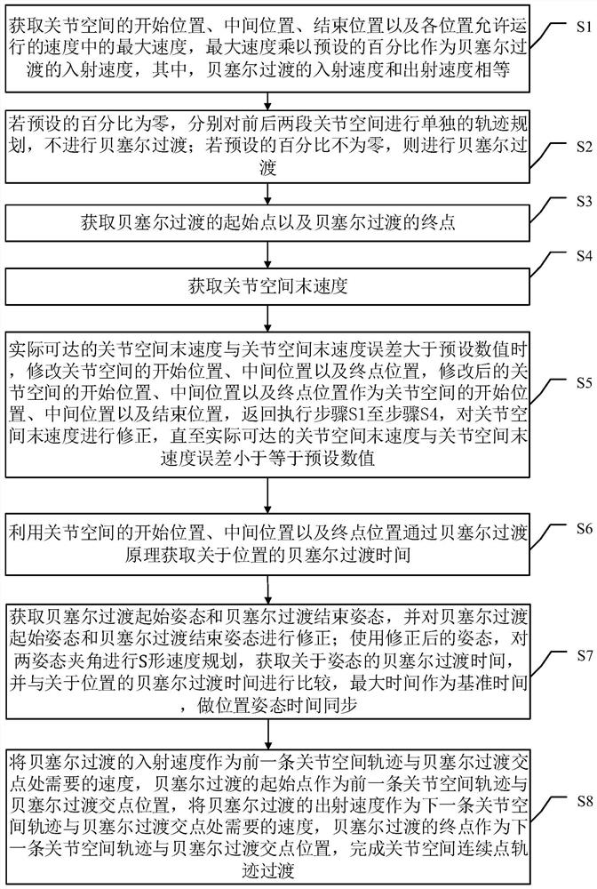
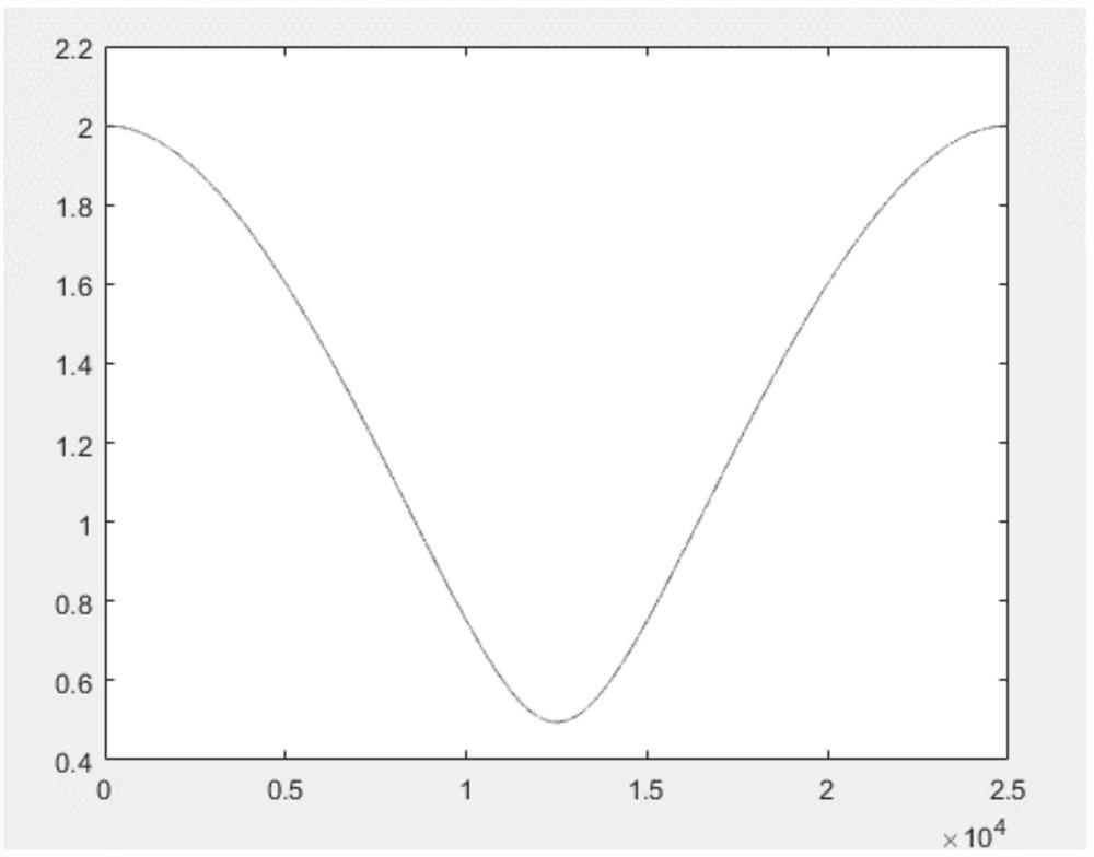
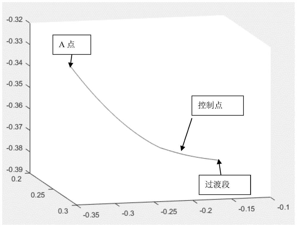
[0051] like figure 1 and figure 2 As shown, a joint space continuous point trajectory transition method, the method includes:

[0052]Step S1: Obtain the maximum velocity of the start position, middle position, and end position of the joint space, and multiply the maximum velocity by a preset percentage as the incoming velocity and outgoing velocity of the Bezier transition, where the incoming velocity and outgoing velocity of the Bezier transition equal speed;

[0053] Step S2: If the preset percentage is zero, perform separate trajectory planning for the front and rear joint spaces without Bezier transition; if the preset percentage is not zero, perform Bezier transition; the specific process is : If the preset percentage is not zero, map the start position q1, middle position q2 and end position q3 of the joint space to the Cartesian space through the mapping relationship to obtain the start position Q1, middle position Q2 and end position Q3 of the Cartesian space, Com...

Embodiment 2

[0075] Corresponding to Embodiment 1, Embodiment 2 of the present invention also provides a joint space continuous point trajectory transition device, which includes:

[0076] The first acquisition module is used to acquire the maximum velocity of the start position, the middle position and the end position of the joint space, and the maximum velocity is multiplied by the preset percentage as the incident velocity and the exit velocity of the Bezier transition, wherein, the Bezier transition The incoming and outgoing velocities are equal;

[0077] The judging module is used to perform separate trajectory planning for the front and rear joint spaces respectively without Bessel transition if the preset percentage is zero; if the preset percentage is not zero, perform Bezier transition;

[0078] The second obtaining module is used to obtain the starting point of the Bezier transition and the end point of the Bezier transition;

[0079] The third obtaining module is used to obtai...


PUM


Abstract

The invention discloses a joint space continuous point track transition method and device. The method comprises the steps that maximum speeds at a starting position, a middle position and an ending position of a joint space are acquired, and the maximum speeds are multiplied by a preset percentage to serve as an incident speed and an emergent speed of Bessel transition; if the preset percentage isnot zero, Bessel transition is performed; a starting point of the Bessel transition and an ending point of the Bessel transition are acquired; the end speed of the joint space is acquired; the end speed of the joint space is corrected until the error between an actual reachable end speed of the joint space and the end speed of the joint space is smaller than or equal to a preset value; Bessel transition time about the position is acquired by utilizing the starting position, the middle position and the ending position of the joint space according to the Bessel transition principle; and position posture time synchronization and joint space continuous point track transition are performed. The method has the advantage that the time cost and the energy consumption cost are reduced.

Description

technical field [0001] The invention relates to the field of motion control of robots, and more particularly relates to a method and device for the trajectory transition of continuous points in joint space. Background technique [0002] The movement space of the manipulator is divided into joint space and Cartesian space. At present, the movement of industrial manipulators in a single joint space and Cartesian space is very easy to realize. The main method of joint space transition is to transfer the joint space to Cartesian space through forward kinematics, and then perform trajectory transition between Cartesian space and Cartesian space instructions, such as reducing the speed to zero at the intersection point, and then switch the space Carry out motion again, can increase time cost and energy consumption cost greatly in actual production like this. For example, for the joint space planning of a general-purpose robot, that is, PTP, each joint is often planned separately ...

Claims


Application Information

Patent Timeline
Patent Type & Authority Applications(China)
IPC IPC(8): B25J9/16
CPCB25J9/1664
Inventor 刘鹏飞杨健刘勋郭龙
Owner 合肥哈工图南智控机器人有限公司
Learn More