Pulse width modulation method suitable for vehicle-mounted motor controller

A pulse width modulation, motor controller technology, used in AC motor control, general control strategies, motors, etc., can solve the problem of unclear reduction of switching frequency, high output voltage/current harmonic content, high harmonic content, etc. problems, to eliminate failure modes, improve safety, and minimize control delays

Active Publication Date: 2021-01-12
LEADRIVE TECH (SHANGHAI) CO LTD
View PDF6 Cites 0 Cited by
  • Summary
  • Abstract
  • Description
  • Claims
  • Application Information

AI Technical Summary

Problems solved by technology

The efficiency of the motor controller and the temperature of the power switching device are affected by many factors, so relying solely on the motor speed cannot guarantee the efficiency of the motor controller, nor can it guarantee that the temperature of the power switching device is within a reliable range
Second, the degree of reduction in switching frequency is not clear
The problem with this control method is that the duty cycle is only updated once per switching cycle. When the motor speed is high, the output voltage / current sine degree is not high, and the harmonic content is large.
Therefore, when the carrier frequency is at the rated value, there is also the problem of high harmonic content of the output voltage / current

Method used


Image

  • Pulse width modulation method suitable for vehicle-mounted motor controller
  • Pulse width modulation method suitable for vehicle-mounted motor controller
  • Pulse width modulation method suitable for vehicle-mounted motor controller

Examples


Embodiment 1

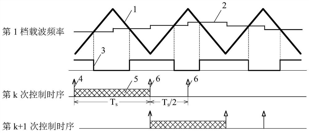
[0071] The following is when the switching frequency is the rated value, and the sampling and calculation can only be triggered at the beginning / end of the rated switching (carrier) period, combined with figure 2 , the specific implementation steps of the pulse width modulation method provided by the present invention are described:

[0072] (1) At the moment shown in Trigger Sampling and Operation 4, that is, at the initial moment of the rated carrier period (the lowest point of the carrier), the instantaneous value of the three-phase output current of the motor controller is exactly equal to the average value within one switching period. At this time, the motor controller starts to collect the state quantities and command values ​​of the motor controller and the motor.

[0073] (2) Further, within the time window shown in Sampling and Operation 5, the switching frequency is determined according to the variable information collected in step (1).

[0074] (3) After that, withi...

Embodiment 2

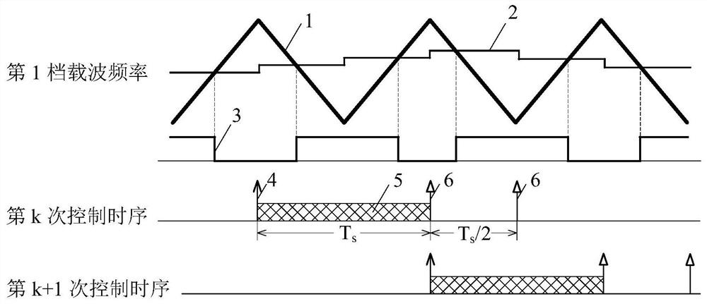
[0080] The following is when the switching frequency is the rated value, and the sampling and calculation can only be triggered at the midpoint of the rated switching (carrier) cycle, combined with image 3 , the specific implementation steps of the pulse width modulation method provided by the present invention are described:

[0081] Different from the above-mentioned embodiment 1, at the moment shown in trigger sampling and operation 4, that is, at the midpoint moment of the rated carrier period (the highest point of the carrier), the instantaneous value of the three-phase output current of the motor controller is exactly equal to average value. At this time, the motor controller starts to collect the state quantities and command values ​​of the motor controller and the motor. The rest of the execution processes are sequentially delayed by half a carrier cycle. In one switching (carrier) cycle, sample once, calculate the voltage command value in the rotating coordinate sy...

Embodiment 3

[0084] The following is when the switching frequency is the rated value, and the sampling and calculation can be triggered at the start / end time and midpoint of the rated switching (carrier) cycle, combined with Figure 4 , the specific implementation steps of the pulse width modulation method provided by the present invention are described:

[0085] Different from Embodiment 1 and Embodiment 2, the motor controller will start to collect the state quantities and command values ​​of the motor controller and the motor at the beginning moment and the midpoint moment of the rated carrier period. Afterwards, the motor controller needs to complete all information collection and calculation within half a carrier period, and update the duty cycle value at the next initial moment or midpoint moment. In one switch (carrier) cycle, sample twice, calculate the voltage command value under the rotating coordinate system twice, obtain the voltage command value under the stationary coordinate...


PUM


Abstract

The invention provides a pulse width modulation method suitable for a vehicle-mounted motor controller, and the method comprises the steps: taking an instruction of the motor controller, the state quantity of the motor controller and the state quantity of a motor as factors, taking at least one of the temperature of a power switching device and the efficiency of the motor controller as an optimization target, and according to the relation between the factors and the optimization target, setting a weight positive/negative number and a weight value of a corresponding factor; judging whether to adjust the switching frequency or not according to each factor and the corresponding weight value; the adjustment degree of the switching frequency is set according to gears, the switching frequency corresponding to each gear is set according to sampling and operation opportunities of a motor controller, and finally, the switching frequency is adjusted to the switching frequency of the corresponding gear according to each factor and the corresponding weight value. According to the method, the purpose of minimizing control delay is achieved, the reduction degree of the switching frequency is determined, the updating rate of the output duty ratio is increased, the sine degree of output voltage/current is improved, and the harmonic content is reduced.

Description

technical field [0001] The present disclosure relates to the technical field of electric vehicle control systems, in particular to a pulse width modulation method suitable for a vehicle-mounted motor controller. Background technique [0002] The motor controller is one of the important components in electric vehicles. One of the core components of the motor controller is the power switching device. By controlling the power switching device to perform high-speed switching operations, the required output voltage / current waveform can be generated. When a power switching device performs a switching action, a certain amount of energy loss is generated, and the energy loss is dissipated on the switching device in the form of heat energy. Therefore, the higher the switching frequency, the greater the switching loss, and the temperature of the switching device will also increase. In order to improve the energy conversion efficiency of the motor controller and ensure that the tempe...

Claims


Application Information

Patent Timeline
Patent Type & Authority Applications(China)
IPC IPC(8): H02P23/28H02P23/00
CPCH02P23/28H02P23/0004Y02T10/72
Inventor 刘光远沈捷韩娜朱骏余浩
Owner LEADRIVE TECH (SHANGHAI) CO LTD
Why Eureka
Try Eureka