Air conditioner directional pipeline type structure connected with mosquito net to conduct cooling or heating
A pipeline-type air conditioner technology, which is applied in the air-conditioning system, pipeline layout, space heating and ventilation, etc., can solve the problems of fast cooling or heating, fast cooling and heating of bed mosquito nets, slow cooling or heating, etc. problems, to achieve the effect of convenient disassembly and assembly, waste reduction, energy saving and energy saving
- Summary
- Abstract
- Description
- Claims
- Application Information
AI Technical Summary
Problems solved by technology
Method used
Image
Examples
Embodiment 1
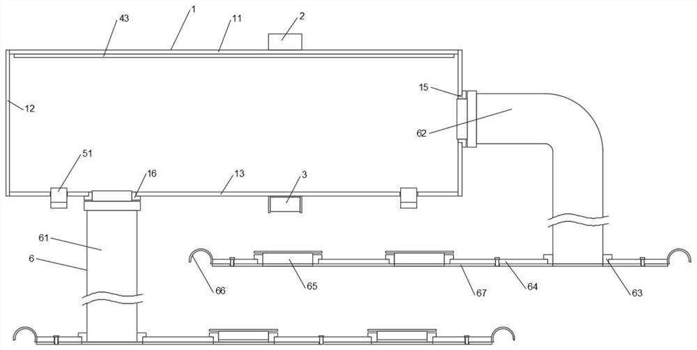
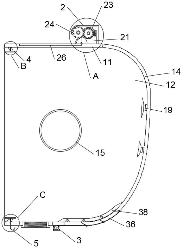
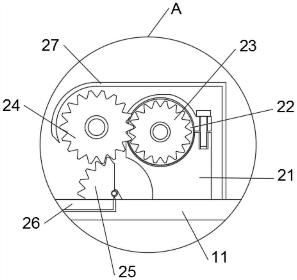
[0037] Such as Figure 1-8 As shown, the present invention provides a kind of structure and the mosquito net body 7 that the directional pipeline type of air conditioner is connected with mosquito net to refrigerate or heat, comprise wind cover mechanism 1, and wind cover mechanism 1 is fixedly installed with air intake control mechanism 2, exhaust air Control mechanism 3, upper card group 4, lower card group 5 and air supply mechanism 6, wind cover mechanism 1 comprises top plate 11, side plate 12, base plate 13 and front cover 14, all vertically fixedly be provided with on the upper end of top plate 11 inner side wall Plate 12, two side plates 12 away from the side of the top plate 11 are vertically fixed on the two ends of the inner wall of the bottom plate 13, the upper side of the inner wall of the front cover 14 is fixedly connected with the top plate 11, the inner side of the front cover 14 The lower side of the wall is fixedly connected with the bottom plate 13, and th...
Embodiment 2
[0040] Such as Figure 4 with Figure 5 As shown, on the basis of Embodiment 1, the present invention provides a technical solution: wherein, the upper card group 4 includes a No. 1 connecting plate 41, and a No. 1 buckle 42 is provided on one side of the No. 1 connecting plate 41. The buckle 42 is bonded with the second buckle 43, the second buckle 43 is fixedly arranged on the inner side wall of the top plate 11, and the side of the first connecting plate 41 away from the first buckle 42 is bonded with double-sided adhesive tape 44, The lower card group 5 includes an elastic card 51, which is installed in the perforation 54 of the shrapnel, and the perforation 54 of the shrapnel is drilled on the side of the bottom plate 13 away from the front cover 14. The No. buckle 52 is arranged on one side of the No. 2 connecting plate 53, and the side of the No. 2 connecting plate 53 away from the No. 3 buckle 52 is bonded with double-sided tape 44, and the side of the two double-side...
Embodiment 3
[0043] Such as figure 1 As shown, on the basis of Embodiment 1, the present invention provides a technical solution: the exhaust pipe 61 is sealed and connected to the lower side panel of the bottom plate 13 through the air outlet interface 16, and the air outlet interface 16 and the bottom plate 13 are sealed and fixed. connection, the air outlet port 16 and the exhaust pipe 61 are threaded and sealed, the air inlet pipe 62 is sealed and connected to the top plate 11 through the air inlet port 15, the air inlet port 15 and the side plate 12 are sealed and fixedly connected, and the air inlet port 15 and the air inlet pipe 62 are threadedly connected.
[0044] In this embodiment, the exhaust pipe 61 and the air inlet pipe 62 are respectively connected between the air outlet port 16 and the air inlet port 15 and the wind shield mechanism 1, which are designed to communicate with the space in the wind shield mechanism 1, This enables the present invention to adjust or select th...
PUM
 Abstract
Description
Claims
Application Information
 - Generate Ideas
- Intellectual Property
- Life Sciences
- Materials
- Tech Scout
- Unparalleled Data Quality
- Higher Quality Content
- 60% Fewer Hallucinations
Browse by: Latest US Patents, China's latest patents, Technical Efficacy Thesaurus, Application Domain, Technology Topic, Popular Technical Reports.
© 2025 PatSnap. All rights reserved.Legal|Privacy policy|Modern Slavery Act Transparency Statement|Sitemap|About US| Contact US: help@patsnap.com


