Lifting handle device

A handle and body technology, applied in the field of inflatable equipment, can solve the problem of single function of the handle

Pending Publication Date: 2021-01-12
MANASLU TECH SHANGHAI CO LTD
View PDF0 Cites 0 Cited by
  • Summary
  • Abstract
  • Description
  • Claims
  • Application Information

AI Technical Summary

Problems solved by technology

[0005] The purpose of the present invention is to provide a handle device to alleviate the technical problem that the function of the handle in the prior art is relatively single

Method used


Image

  • Lifting handle device
  • Lifting handle device
  • Lifting handle device

Examples


Embodiment

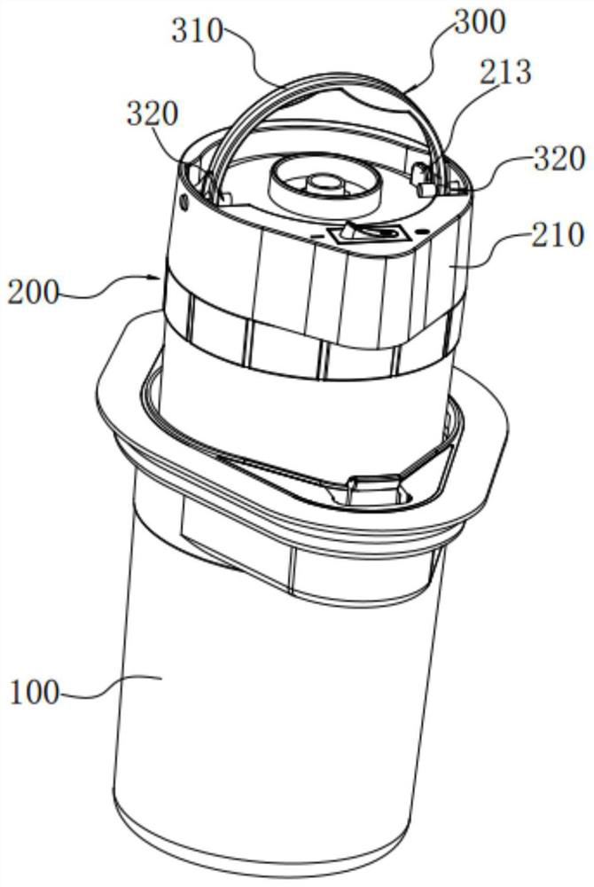
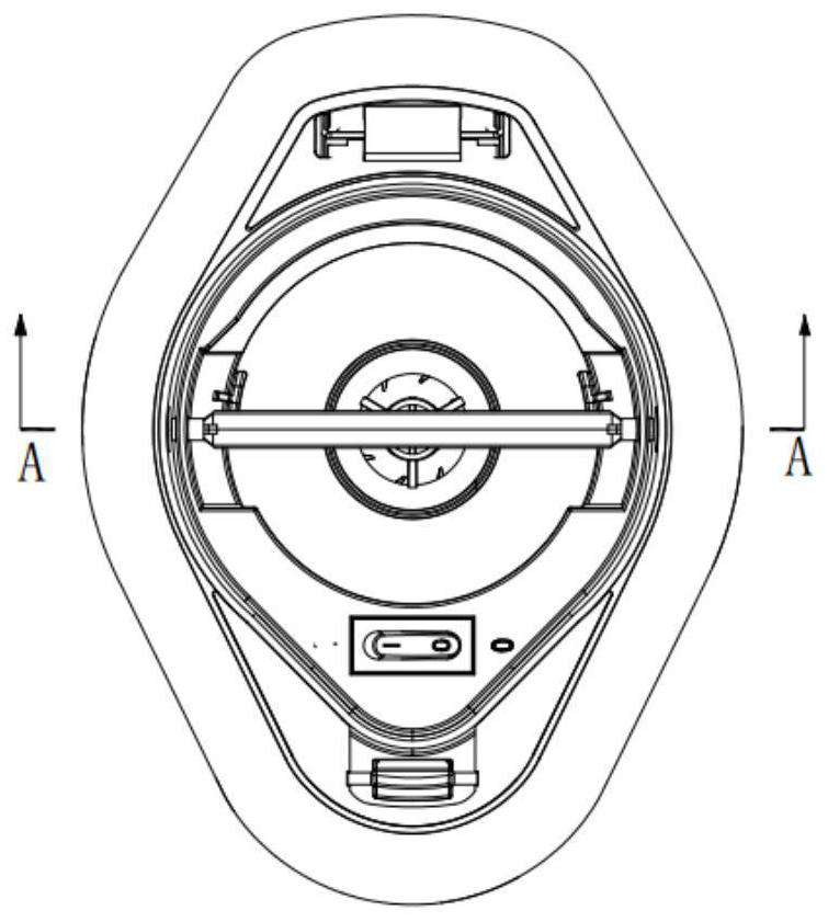
[0045] This embodiment provides a handle device, the handle device includes a body 100, a movement 200 and a buckle 300; the movement 200 is set in the body 100; the buckle 300 includes a handle 310 and The rotating shafts 320 on both sides of the rotating shaft 310 are hinged on the opposite side walls of the movement 200; the handle 310 has a retractable state and a lifting state, and one end of each rotating shaft 320 can be inserted into the side of the body 100 in the retractable state. wall, and can be detached from the side wall of the main body 100 in the lifted state.

[0046] In the handle device provided in this embodiment, the movement 200 is arranged in the body 100, and the buckle 300 includes a handle 310 and a rotating shaft 320. One end of the handle can be plugged into the side wall of the main body 100, so that the movement 200 can be fixed relative to the main body 100. At this time, the movement 200 cannot be pulled out to realize the buckle function; when...


PUM


Abstract

The invention provides a lifting handle device, and relates to the technical field of inflation equipment. The lifting handle device comprises a body, a machine core and a buckling piece; the machinecore is arranged in the body; the buckling piece comprises a lifting handle and rotating shafts fixedly arranged on the two sides of the lifting handle, and the rotating shafts are hinged to the opposite side walls of the machine core; and the lifting handle has a folding and unfolding state and a lifting state, and one end of each rotating shaft can be inserted into the side wall of the body in the folding and unfolding state, and can be separated from the side wall of the body in the lifting state. By means of the lifting handle device, the technical problem that in the prior art, a liftinghandle is single in function is solved.

Description

technical field [0001] The invention relates to the technical field of inflatable equipment, in particular to a handle device. Background technique [0002] With the continuous rapid development of the economy and the continuous improvement of residents' living standards, some outdoor and indoor sports enthusiasts are more and more fond of using inflatable products such as inflatable beds, inflatable sofas or inflatable swimming pools. In general technology, an air pump is usually used to inflate the inflatable product. [0003] Generally, an air pump is mainly composed of a movement (or a battery case). In addition, in order to protect the movement, the movement can also be installed in the body. [0004] However, the air pump provided with the main body in the prior art often has the problem that it is inconvenient to take out the movement. In some technologies, a handle for lifting the movement is provided on the movement, but the function of the handle is relatively s...

Claims


Application Information

Patent Timeline
IPC IPC(8): F04B39/00
CPCF04B39/00
Inventor 唐晓玲秦光英
Owner MANASLU TECH SHANGHAI CO LTD
Why Eureka
Try Eureka