Rolling equipment for packaging bamboo mat
A technology of bamboo mats and equipment, which is applied in the field of rolling equipment for packing bamboo mats, can solve the problems of reduced work efficiency, people's fatigue, troubles, etc.
- Summary
- Abstract
- Description
- Claims
- Application Information
AI Technical Summary
Problems solved by technology
Method used
Image


Examples
Embodiment 1
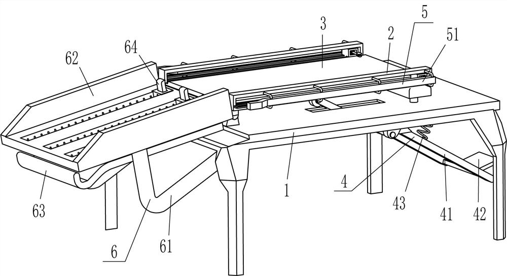
[0024]A winding equipment for bamboo mat packaging, such asFigure 1-Figure 4 As shown, it includes a workbench 1, a return block 2, a placement plate 3, a driving mechanism 4, and a rewinding mechanism 5. The top left side of the workbench 1 is pivotally connected with two return blocks 2, and the front and back sides return A placing plate 3 is fixedly connected between the lower part of the inner side of the block 2, a winding mechanism 5 is provided on the rewinding block 2, and a driving mechanism 4 is provided on the right part of the worktable 1, and the driving mechanism 4 is in contact with the placing plate 3.
[0025]The driving mechanism 4 includes a u-shaped plate 41, a pedal 42 and a first spring 43. The bottom of the workbench 1 is rotatably connected with a u-shaped plate 41 on the right side. The left ends of the u-shaped plate 41 penetrate the workbench 1 and the placement plate 3 The bottom is in contact and fit, a pedal 42 is fixedly connected to the middle of the to...
Embodiment 2
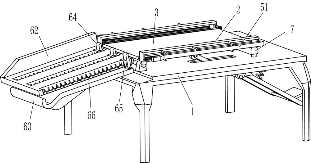
[0031]On the basis of Example 1, such asfigure 1 withfigure 2 As shown, the buffer mechanism 6 is also included. The buffer mechanism 6 includes an L-shaped support rod 61, a U-shaped frame 62, a fixed plate 63, a sliding plate 64, a guide block 65, and a third spring 66. The L-shaped support rod 61 is fixedly connected, and the U-shaped frame 62 is fixedly connected between the top ends of the L-shaped support rods 61 on the front and rear sides. The U-shaped frame 62 is inclined. The U-shaped frame 62 is matched with the placement plate 3, and the U-shaped frame 62 A sliding guide block 65 is connected at the bottom evenly spaced. A third spring 66 is connected between the left side of the guide block 65 and the inside of the U-shaped frame 62. The middle of the guide block 65 is vertically slidable with a sliding plate 64. Workbench 1 A fixing plate 63 is fixedly connected to the left side of the top, and the top of the fixing plate 63 is in contact with the bottom end of the sli...
Embodiment 3
[0034]On the basis of Example 1 and Example 2, such asFigure 3-Figure 5As shown, it also includes a buffer plate 7, a fixed rod 8 and a fourth spring 9. The top right side of the workbench 1 is fixedly connected with three fixed rods 8 evenly spaced, and a buffer plate 7 is slidably arranged between the three fixed rods 8. , The buffer plate 7 cooperates with the return block 2, and a fourth spring 9 is connected between the inside of the buffer plate 7 and the top end of the fixed rod 8.
[0035]It also includes a movable rod 10, a wedge-shaped clamping block 11, and a fifth spring 12. The contact plate 51 has a groove 13 in the middle of the right side of the inner surface of the contact plate 51. The hollow clamping rod 56 is slidably provided with a movable rod 10, and the outer end of the movable rod 10 Located in the groove 13, the top and bottom of the hollow clamping rod 56 are slidably connected with a wedge-shaped clamping block 11, and two fifth springs 12 are connected betw...
PUM
 Abstract
Description
Claims
Application Information
 - R&D
- Intellectual Property
- Life Sciences
- Materials
- Tech Scout
- Unparalleled Data Quality
- Higher Quality Content
- 60% Fewer Hallucinations
Browse by: Latest US Patents, China's latest patents, Technical Efficacy Thesaurus, Application Domain, Technology Topic, Popular Technical Reports.
© 2025 PatSnap. All rights reserved.Legal|Privacy policy|Modern Slavery Act Transparency Statement|Sitemap|About US| Contact US: help@patsnap.com