Plate cutting device
A cutting device and board technology, which is applied to wood processing equipment, forming/shaping machines, manufacturing tools, etc., can solve the problem that the board is easy to move
- Summary
- Abstract
- Description
- Claims
- Application Information
AI Technical Summary
Problems solved by technology
Method used
Image

Examples
Embodiment 1
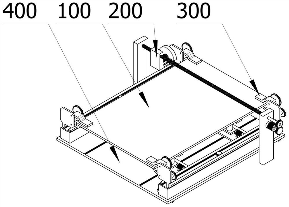
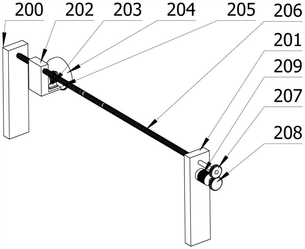
[0050]A plate cutting device includes: a cutting part 200, a clamping part 300, and a moving part 400. The cutting part 200 is used to cut the plate 100. The cutting part 200 has a fixed plate 201, a screw rod 206, a knife holder 202, a first motor 203, a knife cover 204, and a cutting knife 205. There are two fixing plates 201. The fixing plates 201 are arranged symmetrically. The fixing plate 201 is used to fix the cutting part 200; the screw rod 206 is mounted on the fixing plate 201; the knife holder 202 is mounted on the screw rod 206. The screw rod 206 moves left and right; the first motor 203 is installed on the knife holder 202, and the first motor 203 is used to drive the cutting part 200 to cut; the knife cover 204 is a semicircular object, and the inside of the knife cover 204 is hollow, The knife cover 204 and the first motor 203 are in the same axial direction, and the knife cover 204 is mounted on one side of the first motor 203; the cutting knife 205 is mounted in the...
Embodiment 2
[0060]A plate cutting device includes: a cutting part 200, a clamping part 300, and a moving part 400. The cutting part 200 is used to cut the plate 100. The cutting part 200 has a fixed plate 201, a screw rod 206, a knife holder 202, a first motor 203, a knife cover 204, and a cutting knife 205. There are two fixing plates 201. The fixing plates 201 are arranged symmetrically. The fixing plate 201 is used to fix the cutting part 200; the screw rod 206 is mounted on the fixing plate 201; the knife holder 202 is mounted on the screw rod 206. The screw rod 206 moves left and right; the first motor 203 is installed on the knife holder 202, and the first motor 203 is used to drive the cutting part 200 to cut; the knife cover 204 is a semicircular object, and the inside of the knife cover 204 is hollow, The knife cover 204 and the first motor 203 are in the same axial direction, and the knife cover 204 is mounted on one side of the first motor 203; the cutting knife 205 is mounted in the...
Embodiment 3
[0074]A method for cutting a plate includes the following steps:
[0075]In transportation, the plate 100 is transported to the plate cutting device through a conveyor, and the cylinder 505 is activated to raise the support 506 below the plate 100 to hold the plate 100 to prevent the plate 100 from falling;
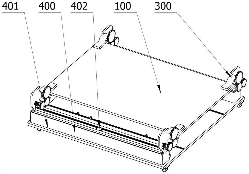
[0076]After the plate 100 is moved to the designated place, the fourth motor 408 is activated to telescopically move the clamping part 300. When it moves to the end of the plate 100, the fourth motor 408 is turned off and the clamping part 300 stops moving. The motor 304 is activated to drive the third gear 303 to rotate, thereby driving the fourth gear 305 meshing with the third gear 303 to rotate, thereby driving the fifth gear 306 meshing with the fourth gear 305 to rotate, thereby making the fourth gear The first gripping hand 307 and the second gripping hand 308 on the gear 305 and the fifth gear 306 perform clamping movements in opposite directions to clamp the plate 100;
[0077]...
PUM
 Abstract
Description
Claims
Application Information
 - R&D
- Intellectual Property
- Life Sciences
- Materials
- Tech Scout
- Unparalleled Data Quality
- Higher Quality Content
- 60% Fewer Hallucinations
Browse by: Latest US Patents, China's latest patents, Technical Efficacy Thesaurus, Application Domain, Technology Topic, Popular Technical Reports.
© 2025 PatSnap. All rights reserved.Legal|Privacy policy|Modern Slavery Act Transparency Statement|Sitemap|About US| Contact US: help@patsnap.com