
Oil-immersed transformer end insulation automatic bonding machine

An oil-immersed transformer and terminal insulation technology, which is applied in the direction of inductance/transformer/magnet manufacturing, coil manufacturing, electrical components, etc., can solve the problems of large iron core, waste of time, and inconvenient pasting of insulating paper, so as to save manpower, paste simple effects

Pending Publication Date: 2021-01-08
康利源科技(天津)股份有限公司
View PDF0 Cites 4 Cited by
  • Summary
  • Abstract
  • Description
  • Claims
  • Application Information

AI Technical Summary

Problems solved by technology

In the process of assembling oil-immersed transformers, it is necessary to paste insulating paper on the outer wall of the iron core, but the existing insulating paper is pasted manually, which not only wastes time, but also causes insulation problems due to the large volume of the iron core of some transformers. Paper sticking is very inconvenient

Method used


Image

  • Oil-immersed transformer end insulation automatic bonding machine
  • Oil-immersed transformer end insulation automatic bonding machine
  • Oil-immersed transformer end insulation automatic bonding machine

Examples


Embodiment 1

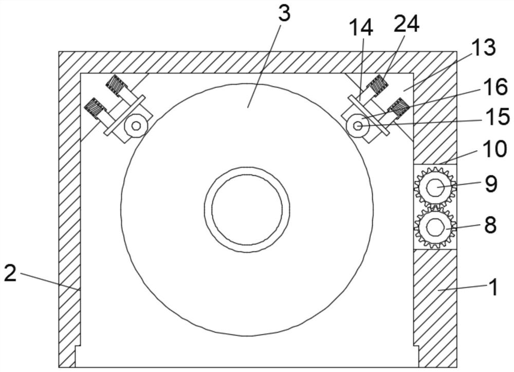
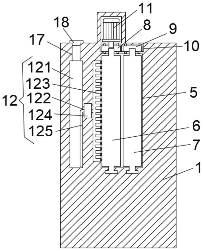
[0022] see figure 1 , figure 2 , image 3 , Figure 4 and Figure 5 , the present invention provides a technical solution: an oil-immersed transformer end insulation automatic bonding machine, including a main body 1, a bonding chamber 2 is opened on the front side wall of the main body 1, and a lower side wall of the bonding chamber 2 is rotatably connected with a rotating Table 3, the rotating table 3 is used to place the iron core of the transformer, the lower side wall of the rotating table 3 is fixedly connected with the first motor 4, the rotating table 3 is driven by the first motor 4 to rotate, and the first motor 4 is fixedly installed on the main body 1 The inner cavity of the bonding chamber 2 is provided with an insulating paper input groove 5 on the right side wall of the adhesive chamber 2, and the first roller 6 and the second roller 7 are rotatably connected in the insulating paper input groove 5 The top of 7 is fixedly installed with first gear 8 and seco...

Embodiment 2

[0028] see Figure 6 , Figure 7 and Figure 8 The difference between the technical solution provided by the present invention and the technical solution in Embodiment 1 is that a rotating ring 19 is rotatably connected in the glue tank 121, and the center of the rotating ring 19 is fixedly connected with a fixed shaft 21 through a connecting shaft 20. , the side wall of the fixed shaft 21 is fixedly equipped with a stirring rod 22, and a linkage device 23 is fixedly installed between the side wall of the rotating ring 19 and the side wall of the first gear 8. After the first gear 8 rotates, the linkage device 23 drives The rotating ring 19 rotates, so that the stirring rod 22 stirs the glue in the glue tank 121 to ensure that the glue has better fluidity.

[0029] Linkage device 23 comprises transmission shaft 231, and transmission shaft 231 is fixedly installed in the inner cavity of main body 1, and the bottom end of transmission shaft 231 is meshed with rotating ring 19,...


PUM


Abstract

The present invention discloses an oil-immersed transformer end insulation automatic bonding machine. The oil-immersed transformer end insulation automatic bonding machine comprises a main body, a bonding cavity is formed in the front side wall of the main body, the lower side wall of the bonding cavity is rotationally connected with a rotating table, the lower side wall of the rotating table is fixedly connected with a first motor, the first motor is fixedly installed in an inner cavity of the main body, and an insulation paper input groove is formed in the right side wall of the bonding cavity; the first gear and the second gear are located in the driving cavity, the first motor drives the rotating table to rotate, the second motor drives the first roller to rotate so that insulation paper can enter the bonding cavity, then the first roller is glued through the gluing device so that the insulation paper can be bonded to the side wall of the iron core, and then the insulation paper isextruded through the extrusion roller. By means of the iron core insulation paper pasting device, pasting of the iron core insulation paper can be simpler and more convenient, and manpower and material resources are saved.

Description

technical field [0001] The invention relates to the technical field of transformer production, in particular to an oil-immersed transformer terminal insulation automatic bonding machine. Background technique [0002] Oil-immersed transformer is a new type of high-performance transformer with more reasonable structure and better performance. The three-dimensional wound iron core has three-dimensional arrangement of equilateral triangles, so there is no air gap in the magnetic circuit and the winding is more compact. . In the process of assembling oil-immersed transformers, it is necessary to paste insulating paper on the outer wall of the iron core, but the existing insulating paper is pasted manually, which not only wastes time, but also causes insulation problems due to the large volume of the iron core of some transformers. Pasting of paper is very inconvenient. For this reason, we propose an oil-immersed transformer terminal insulation automatic bonding machine. Conte...

Claims


Application Information

Patent Timeline
Patent Type & Authority Applications(China)
IPC IPC(8): H01F41/12B05C13/02B05C1/02
CPCH01F41/125B05C13/02B05C1/02
Inventor 孙忠海赵文忠刘俊孙赫丁杨孙忠河李旭孙忠江
Owner 康利源科技(天津)股份有限公司
Learn More