Tipping bucket type rain gauge

A tipping bucket rain gauge and rain sensing technology, which is applied in rainfall/precipitation gauges, measuring devices, meteorology, etc., can solve the problems that the tipping bucket cannot be turned over correctly and in time, the rainfall measurement is inaccurate, and the reed switch is damaged. Achieve the effect of improving measurement accuracy, meeting precise measurement requirements, and reducing the use of fasteners

Pending Publication Date: 2021-01-08
孙纯虎 +1
View PDF0 Cites 1 Cited by
  • Summary
  • Abstract
  • Description
  • Claims
  • Application Information

AI Technical Summary

Problems solved by technology

[0002] The structure of the existing tipping bucket rain gauge is generally composed of a bracket, a tipping bucket, a measuring tipping bucket and a counting tipping bucket. The assembly is relatively complicated. The structure of the bracket is also relatively complicated. When measuring heavy rainfall, because most of the existing rain gauges use a single tipping bucket design, a large amount of rainwater entering the tipping bucket for a short time may cause the tipping bucket to fail to be turned over correctly and in time, resulting in The rainwater in the tipping bucket is lost, so the rain gauge cannot measure the rainwater currently entering the tipping bucket, which eventually leads to inaccurate rainfall measurement and poor precision. In terms of accuracy adjustment, most of the existing tipping bucket rain gauges use left and right Two thimble screws are used to adjust the error. Since both sides need to be adjusted at the same time, it is very inconvenient to adjust. On the other hand, the existing reed switch is fixedly installed in the narrow space between the counting bucket and the metering bucket. In the long-term rainfall measurement process, it is inevitable that the reed switch will be damaged, and the reed switch in the above design cannot be replaced in time and conveniently.

Method used


Image

  • Tipping bucket type rain gauge
  • Tipping bucket type rain gauge
  • Tipping bucket type rain gauge

Examples


Embodiment Construction

[0016] In order to make the technical means, innovative features and functions realized by the present invention easy to understand, the present invention will be further described below.

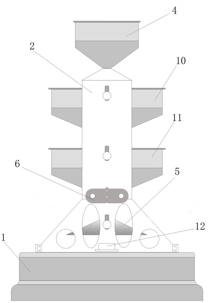
[0017] Such as Figure 1-Figure 5 As shown, the technical solution of the tipping bucket rain gauge of the present invention includes a base 1, a gantry support 2 fixedly formed on the base 1, a support 3 fixed on the top of the gantry support 2, and the bottom passes through the support 3 and is fixed. The rain funnel 4 installed on the support 3, the multiple tipping buckets reversibly installed on the gantry support 2, the measuring tipping bucket reversibly installed on the bottom of the gantry support 2, and the rain sensing mechanism fixedly installed on the gantry support 2 6. An output terminal and a one-point positioning mechanism connected and coordinated with the rainfall sensing mechanism 6. The gantry bracket 2 includes an integrally formed gantry left bracket 2.1 and a gantry ...


PUM


Abstract

The invention discloses a tipping bucket type rain gauge. The gauge comprises a base, a gantry support fixedly arranged on the base and integrally formed, a support fixedly arranged at the top of thegantry support, a rain bearing funnel having the bottom penetrating through the support and fixedly installed on the support, a plurality of tipping buckets and metering buckets installed on the gantry support in a turnover mode, a rainfall induction mechanism fixedly installed on the gantry support, an output terminal connected and matched with the rainfall induction mechanism and one-point positioning mechanisms. The tipping buckets are installed on the gantry support in a turnover mode from top to bottom from the position below an outlet in the bottom of the rain bearing funnel through a plurality of pairs of tipping bucket supporting points, and longitudinal positioning grooves and the one-point positioning mechanism are further installed at the installation positions of the metering buckets of the gantry support. And the rainfall induction mechanism is located between the metering buckets and the tipping buckets above the metering tipping buckets, measures and counts rainfall andtransmits a result to the output terminal for final output of a rainfall numerical value. The gauge has the advantages of small rainfall metering error, high precision and simple structure.

Description

technical field [0001] The invention relates to the field of rainfall monitoring, in particular to a tipping bucket rain gauge. Background technique [0002] The structure of the existing tipping bucket rain gauge is generally composed of a bracket, a tipping bucket, a measuring tipping bucket and a counting tipping bucket. The assembly is relatively complicated. The structure of the bracket is also relatively complicated. When measuring heavy rainfall, because most of the existing rain gauges use a single tipping bucket design, a large amount of rainwater entering the tipping bucket for a short time may cause the tipping bucket to fail to be turned over correctly and in time, resulting in The rainwater in the bucket is lost, so the rain gauge cannot measure the rainwater currently entering the tipping bucket, which eventually leads to inaccurate rainfall measurement and poor precision. In terms of precision adjustment, most of the existing tipping bucket rain gauges use lef...

Claims


Application Information

Patent Timeline
IPC IPC(8): G01W1/14
CPCG01W1/14
Inventor 孙纯虎胡庆钢
Owner 孙纯虎
Why Eureka
Try Eureka