Lower end hydraulic support for steep slope tunnel and application method

A technology of hydraulic support and end support, which is applied in the direction of mine roof support, earth square drilling, mining equipment, etc. It can solve the problems of dynamic longitudinal unbalance, bite frame, static lateral instability, etc., and achieve simple support structure and easy installation. Easy to place effects

Pending Publication Date: 2020-10-16
宁波精壹机械制造有限公司
View PDF0 Cites 0 Cited by
  • Summary
  • Abstract
  • Description
  • Claims
  • Application Information

AI Technical Summary

Problems solved by technology

Due to the large inclination angle of the steeply inclined coal seam, the traditional hydraulic support structure determines that the hydraulic support of the steeply inclined coal seam working face is always in a state of static lateral instability and dynamic longitudinal imbalance under normal working conditions. If the hydraulic support loses the effective support of the lower hydraulic support, the moved hydraulic support will immediately topple over, ranging from biting the lower hydraulic support to the lower hydraulic support, and in severe cases, the moved hydraulic support will be inverted, directly causing a roof fall accident. The inclined coal seam is generally in the roadway, that is, there is a sharply inclined coal seam in the straight roadway. Therefore, along the coal seam, a coal mining roadway needs to be excavated. The coal mining roadway is a steeply inclined roadway, and hydraulic support supports are placed side by side in the steeply inclined roadway. , these support brackets are used to support the top of the coal mining roadway to prevent the top from collapsing, and the head and tail of the whole row of support brackets are located at the entrance and exit of the steeply inclined roadway, especially at the exit, because the hydraulic supports in the steeply inclined roadway are side by side When stacking, the overall center of gravity and weight need to be supported by a supporting base, and the position of the exit of the steeply inclined roadway is very important. Once a roof falls or collapses there, the entire coal mining roadway will fall short. Therefore, there is an urgent need for a solid The base of the hydraulic support that supports the mouth of the steeply inclined coal seam and can firmly cooperate with the hydraulic support in the roadway of the steeply inclined coal seam

Method used


Image

  • Lower end hydraulic support for steep slope tunnel and application method
  • Lower end hydraulic support for steep slope tunnel and application method

Examples


Embodiment 1

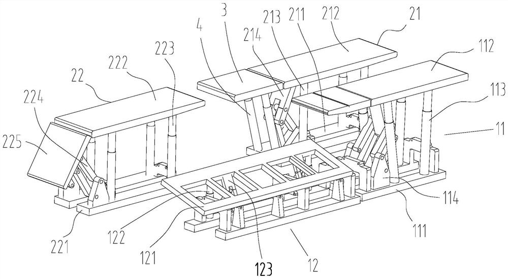
[0025] Embodiment one, such as figure 1 , 2 As shown, the structure of the present invention includes a first support 1 and a second support 2, both of which are located at the exit at the bottom of the steeply inclined roadway.

[0026] The first support 1 includes a terminal support 11 and a sliding runway 12, the terminal support 11 and the sliding runway 12 are arranged in close proximity, and the sliding runway 12 is close to the exit at the bottom of the steeply inclined roadway.

[0027] The end bracket 11 includes a first base 111, a first support beam 112, a first oil cylinder 113 and a first linkage 114, the first support beam 112 is fixed above the first base 111 by the first oil cylinder 113, and the first oil cylinder 113 One end is hinged or fixed to the first base 111, and the other end is hinged to the first support beam 112. The first support beam 112 expands and contracts through the first oil cylinder 113 to realize lifting action. The first linkage mechani...

Embodiment 2

[0036] In the second embodiment, the support slide 121 is hinged to the first base 111 through a support column, that is, one end of the support column is fixed to the first base 111, and the other end is hinged to the support slide. According to different actual working conditions, support columns of different heights are used to increase the The stability of the sliding runway 12 is improved, and the supporting slide plate 121 can flexibly swing at different angles to adapt to sharply inclined roadways at different angles. All the other are the same as embodiment one.

Embodiment 3

[0037] Embodiment 3, the first base 111 is divided into two parts, one part is the base of the end support 11, and the other part is used to fix the sliding track 12, and a telescopic oil cylinder is arranged between the two parts of the base, and the oil cylinder is respectively fixed on the two parts The base realizes the adjustment of the distance between the two parts of the base through the expansion and contraction of the oil cylinder, so that the distance between the end support 11 and the sliding track 12 can be adjusted more flexibly. All the other are the same as embodiment one.

[0038] The first base 111, the second base 211 and the third base 221 can add frame box-type bases, that is, set a frame box-type base on each base, so that pedestrian passages can be added in the bases, and isolation nets and escalators are used. And other devices are fixed on the base frame by welding to allow personnel to enter and exit, while preventing gravel or sundries from falling i...


PUM


Abstract

The invention discloses a lower end hydraulic support for a steep slope tunnel and an application method. The lower end hydraulic support for steep slope tunnel comprises a first support and a secondsupport which are both located at an exit of the bottom of the steep slope tunnel. The first support comprises an end support and a sliding runway. The end support and the sliding runway are arrangedfront and back adjacently. The sliding runway gets close to the exit of the bottom of the steep slope tunnel. The second support comprises a front support and a rear support. The front support and therear support are arranged front and back adjacently. The end support and the front support are arranged adjacently side by side. The sliding runway and the rear support are arranged adjacently side by side. The lower end hydraulic support is located at the exit of the steep slope tunnel and used for supporting the top face of the exit of the steep slope tunnel and can protect the top face againstcollapse or rock falling and ensure the going-in and coming-out safety of staff or coal mining safety.

Description

technical field [0001] The invention relates to the technical field of coal mining, and more specifically relates to a lower end hydraulic support for a steeply inclined roadway and a use method thereof. Background technique [0002] When the inclination angle of the coal seam roadway is greater than or equal to 45°, the coal seam is a steeply inclined coal seam. Due to the large inclination angle of the steeply inclined coal seam, the traditional hydraulic support structure determines that the hydraulic support of the steeply inclined coal seam working face is always in a state of static lateral instability and dynamic longitudinal imbalance under normal working conditions. If the hydraulic support loses the effective support of the lower hydraulic support, the moved hydraulic support will immediately topple over, ranging from biting the lower hydraulic support to the lower hydraulic support, and in severe cases, the moved hydraulic support will be inverted, directly causin...

Claims


Application Information

Patent Timeline
IPC IPC(8): E21D23/04E21D23/03E21D23/00
CPCE21D23/0082E21D23/03E21D23/0409
Inventor 刘佳军郭夕祥
Owner 宁波精壹机械制造有限公司
Why Eureka
Try Eureka