
Plane cutter of plane armoring mechanism

A cutter and plane technology, applied in welding equipment, laser welding equipment, metal processing equipment, etc., can solve problems affecting cutting effects, economic losses, air pollution, etc., to protect health, avoid economic losses, and purify the production environment Effect

Pending Publication Date: 2021-01-08
ANHUI AOYU CNC TECH +1
View PDF0 Cites 0 Cited by
  • Summary
  • Abstract
  • Description
  • Claims
  • Application Information

AI Technical Summary

Problems solved by technology

[0003] 1. During laser cutting, the cutting parts will be vaporized, which will generate smoke and dust, especially the armor mechanism, which contains more particles. However, most of the current cutters are terrace-type, and the smoke and dust will inevitably be inhaled by the operator, which will also pollute the production. air in the environment
[0004] 2. When the armor mechanism is cut, the cutting precision is very high. Due to the diversity of the production environment, the current cutter cannot guarantee the levelness of the cutting surface. When the cutting table is inclined, it will inevitably affect the cutting effect, resulting in the The workpiece cannot be used, causing economic losses

Method used


Image

  • Plane cutter of plane armoring mechanism
  • Plane cutter of plane armoring mechanism
  • Plane cutter of plane armoring mechanism

Examples


Embodiment Construction

[0021] The following will clearly and completely describe the technical solutions in the embodiments of the present invention with reference to the accompanying drawings in the embodiments of the present invention. Obviously, the described embodiments are only some of the embodiments of the present invention, not all of them. Based on the embodiments of the present invention, all other embodiments obtained by persons of ordinary skill in the art without making creative efforts belong to the protection scope of the present invention.

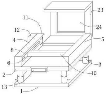
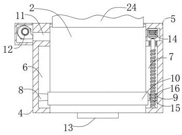
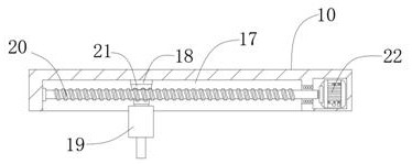
[0022] see Figure 1-4 , the present invention provides a technical solution: a plane cutter with a plane armor mechanism, comprising a fixed base 1 and a cutting table 2, the four corners of the top surface of the fixed base 1 are affixed to the bottom of the level adjustment assembly 3, and the top of the level adjustment assembly 3 is affixed to the cutting table. The table 2 and the two sides of the top surface of the cutting table 2 are fixe...


PUM


Abstract

The invention discloses a plane cutter of a plane armoring mechanism. The cutter comprises a fixed base and a cutting table, the four corners of the top face of the fixed base are fixedly connected with the bottoms of horizontal adjusting assemblies, the tops of the horizontal adjusting assemblies are fixedly connected with the cutting table, the two sides of the top face of the cutting table arefixedly connected with a left support and a right support correspondingly, and a left sliding groove is formed in the left support; a left sliding block is connected into the left sliding groove in asliding manner, a right sliding groove is formed in the right support, and a right sliding block is connected into the right sliding groove in a sliding manner; and the cutter is provided with a dustoutlet and a draught fan, smoke dust generated in the cutting process can be discharged, the production environment is purified, and the body health of an operator is protected. The angle of the cutting table can be adjusted through the horizontal adjusting assemblies, whether the cutting table is located at the horizontal position or not is judged through a horizontal liquid level instrument, thesituation that a cut workpiece cannot be used due to inclination of the cutting table is avoided, the yield is guaranteed, and economic losses are avoided.

Description

technical field [0001] The invention relates to the technical field of military equipment, in particular to a plane cutter for a plane armor mechanism. Background technique [0002] In the production process of modern military industry, it is often necessary to cut the armor mechanism. Due to the high hardness and thickness of the armor mechanism, laser cutters are generally used for cutting. Laser cutting uses high-power-density laser beams to irradiate the cut material, making the material very It is quickly heated to the vaporization temperature, and evaporates to form holes. With the movement of the beam to the material, the holes continuously form a narrow slit (such as about 0.1mm) to complete the cutting of the material. The current laser cutter has the following defect: [0003] 1. During laser cutting, the cutting parts will be vaporized, which will generate smoke and dust, especially the armor mechanism, which contains more particles. However, most of the current ...

Claims


Application Information

Patent Timeline
Patent Type & Authority Applications(China)
IPC IPC(8): B23K26/38B23K26/142B23K26/70B23K26/08
CPCB23K26/38B23K26/142B23K26/0876B23K26/702
Inventor 徐昆刘谦
Owner ANHUI AOYU CNC TECH
Learn More