Anti-loosening femoral stem prosthesis
A femoral stem, loose technology, applied in the direction of prosthesis, femur, femoral head, etc., can solve the problems of femoral stem prosthesis and femoral medullary cavity loosening, affecting patients' normal life, economic pressure, etc.
- Summary
- Abstract
- Description
- Claims
- Application Information
AI Technical Summary
Problems solved by technology
Method used
Image

Examples
Embodiment 1
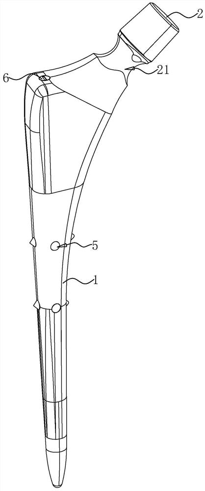
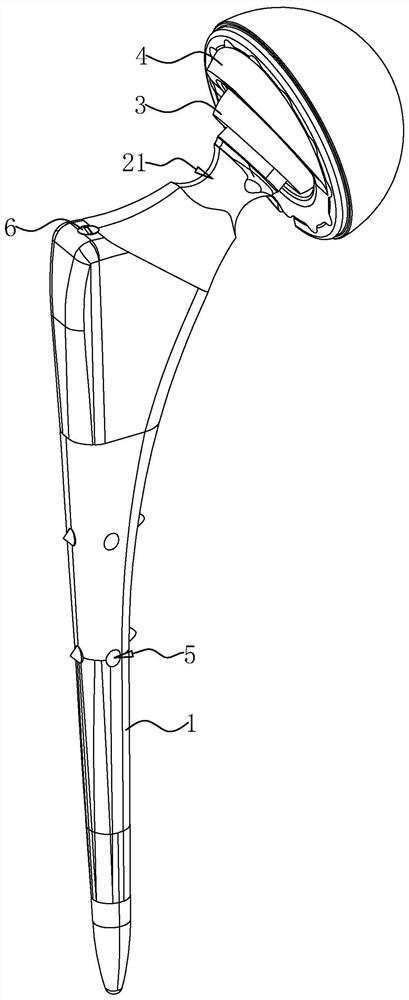
[0036] The embodiment of the present application discloses a loosening-proof femoral stem prosthesis. refer to figure 1 and figure 2 , the femoral stem prosthesis includes a femoral stem body 1 and a femoral neck 2; one end of the femoral stem body 1 is the proximal end of the femoral stem, the other end is the distal end of the femoral stem, and the femoral neck 2 is integrally connected to the proximal end of the femoral stem. The outer wall of the neck 2 is provided with a ring-shaped relief groove 21. The setting of the relief groove 21 enables the femoral stem prosthesis to have a greater range of motion after being assembled with the acetabular cup 3, allowing the patient to perform larger movements. The sports movement of angle has reduced the possibility that femoral stem prosthesis and liner 4 collide.
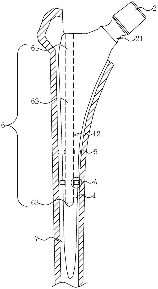
[0037] refer to image 3 , the femoral stem body 1 is provided with an inserter and two groups of movable parts 5, wherein, the inserter can be vertically inserte...
Embodiment 2
[0042] The embodiment of the present application discloses a kind of anti-loosening type femoral stem prosthesis, refer to Figure 5The difference between this embodiment and Embodiment 1 lies in the movable part. The movable part 5 includes a slide bar 51 arranged in the guide hole 11. The end of the slide bar 51 near the insert is processed with a first tapered head 52. The guide hole 11 A guide sleeve 8 communicated with it is embedded inside, and the inner wall of the guide sleeve 8 and the outer wall of the slide bar 51 are all processed with rough surfaces, so that the friction between the guide sleeve 8 and the slide bar 51 is greater than the gravity of the movable part 5, Prevent slide bar 51 from sliding freely.
[0043] One end of the slide bar 51 away from the first conical head 52 is provided with a groove 511, and a push rod 54 is slidably arranged in the groove 511, and the push rod 54 is located between one end in the groove 511 and the inner bottom wall of the...
PUM
 Abstract
Description
Claims
Application Information
 - R&D
- Intellectual Property
- Life Sciences
- Materials
- Tech Scout
- Unparalleled Data Quality
- Higher Quality Content
- 60% Fewer Hallucinations
Browse by: Latest US Patents, China's latest patents, Technical Efficacy Thesaurus, Application Domain, Technology Topic, Popular Technical Reports.
© 2025 PatSnap. All rights reserved.Legal|Privacy policy|Modern Slavery Act Transparency Statement|Sitemap|About US| Contact US: help@patsnap.com