
Centrifugal separator

A centrifugal separator and separator technology, which can be used in centrifuges, centrifuges with rotating drums, dairy products, etc., and can solve problems such as reduced efficiency and reduced degreasing performance.

Active Publication Date: 2021-01-05
TETRA LAVAL HLDG & FINANCE SA
View PDF13 Cites 0 Cited by
  • Summary
  • Abstract
  • Description
  • Claims
  • Application Information

AI Technical Summary

Problems solved by technology

The problem with existing separators is that they become less efficient under certain operating conditions
For example, degreasing performance may decrease at low temperatures

Method used


Image

  • Centrifugal separator
  • Centrifugal separator
  • Centrifugal separator

Examples


Embodiment Construction

[0013] Embodiments of the invention will now be described more fully hereinafter with reference to the accompanying drawings, in which some, but not all embodiments of the invention are shown. This invention may be embodied in many different forms and should not be construed as limited to the embodiments set forth herein.

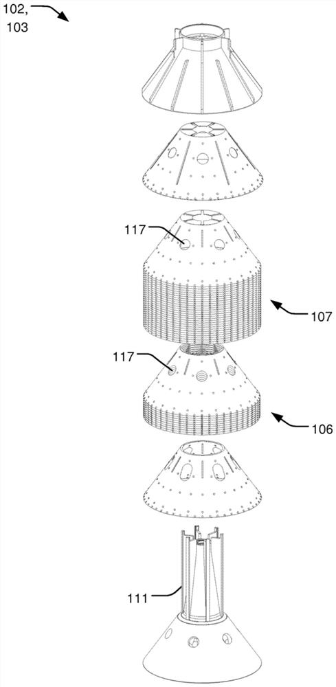
[0014] figure 1 is a schematic diagram of a separator 100 for separating milk (RM) into a cream phase (CR) and a skim milk phase (SM). The separator 100 comprises a centrifuge bowl 101 and a disk stack 102 of conical disks 103 arranged within the centrifuge bowl 101 . Milk (RM), commonly referred to as raw milk, enters the centrifuge bowl 101 via inlet 113 and is subsequently separated at the top of the centrifuge bowl 101 into a skim milk phase (SM) and a cream phase (CR). That is, milk (RM) flows from inlet 113 into distribution opening 117 in disc stack 102, and cream phase (CR) is centrifuged towards and flows from center portion 118 or disc stack 102...


PUM


Abstract

A centrifugal separator (100) for separating milk (RM) into a cream phase (CR) and a skim milk phase (SM) is disclosed. The separator (100) comprises a centrifuge bowl (101), a disc stack (102) of conical discs (103) arranged inside the centrifuge bowl (101). The disc stack (102) comprises a first set of discs (106) and a second set of discs (107), the discs (103) in the disk stack (102) comprisesdistribution openings (117) such that the milk (RM) passes the first set of discs (106) before passing the second set of discs (107). The discs in the first set of discs (106) are separated from eachother by a first distance (108), and the discs in the second set of discs (107) are separated from each other by a second distance (109) which is smaller than the first distance (108).

Description

technical field [0001] The invention relates to a centrifugal separator for separating milk into a cream phase and a skim milk phase, and a method for separating cold milk. Background technique [0002] A separator that separates milk into different phases of different densities under the influence of centrifugal force is called a centrifugal separator. The milk is introduced into a rotating disc stack of a centrifugal separator. Under the influence of centrifugal force, the heavier components and lighter fat globules in raw milk start to settle radially outwards and inwards according to their respective densities. Cream (ie fat globules) has a lower density than skim milk and therefore moves inwards on the disc, towards the axis of rotation of the separator. The cream continues to the axial outlet, and the heavier phase, skim milk, moves outward to the space outside the stack and from there to the skim milk outlet. A problem with existing separators is that efficiency de...

Claims


Application Information

Patent Timeline
Patent Type & Authority Applications(China)
IPC IPC(8): B04B1/08B04B7/14
CPCB04B1/08B04B7/14A23C9/14
Inventor 凯文·斯汀格尔米卡埃尔·松德格伦
Owner TETRA LAVAL HLDG & FINANCE SA
Learn More