Eureka AIR delivers breakthrough ideas for toughest innovation challenges, trusted by R&D personnel around the world.

Test shielding box for 5G communication

A technology of shielding box and main body, which is applied in the direction of shielding efficiency measurement, magnetic field/electric field shielding, and containers for preventing mechanical damage. It can solve the problems of unable to adjust the support of the shielding box, unable to adjust and control the plane state of the shielding box, and vibration of internal precision instruments.

Inactive Publication Date: 2021-01-05
李庆磊
View PDF1 Cites 1 Cited by
  • Summary
  • Abstract
  • Description
  • Claims
  • Application Information

AI Technical Summary

Problems solved by technology

[0005] In order to solve the above technical problems, the present invention provides a test shielding box for 5G communication, to solve the problem that when the existing signal test shielding box is used, it is usually used in an uneven position on the mountain, and the shielding box cannot be placed and used. The support adjustment of the box can not be adjusted according to the terrain to control the shielding box to be in a flat state, and when the existing signal test shielding box is in use, when transporting internal equipment, it is easy to transport on mountain roads and dirt roads, and it is easy to make the inside of the shielding box Vibration is generated, which easily causes vibration problems for internal precision instruments

Method used


Image

  • Test shielding box for 5G communication
  • Test shielding box for 5G communication
  • Test shielding box for 5G communication

Examples


Embodiment Construction

[0030]Embodiments of the present invention will be further described in detail below in conjunction with the accompanying drawings and examples. The following examples are used to illustrate the present invention, but should not be used to limit the scope of the present invention.

[0031] as attached figure 1 to attach Figure 8 Shown:

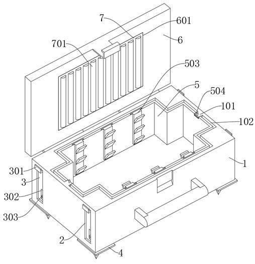
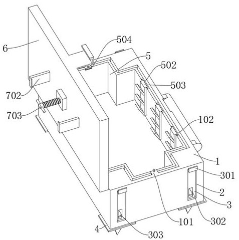
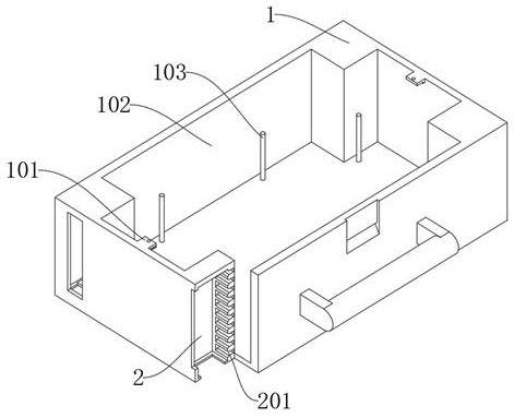
[0032] The present invention provides a test shielding box for 5G communication, including a main body 1, an adjustment slot 2, an adjustment rod 3, a bottom part 4, a placement part 5, a flip plate 6 and an adjustment plate 7; the main body 1 is the shielding box body, and The main body 1 is a rectangular structure; the adjustment groove 2 is arranged at the bottom corner of the main body 1; the bottom piece 4 is installed on the bottom of the adjustment rod 3, and the connector 401 of the bottom piece 4 is embedded in the inside of the connection groove 304, and the connector The limit groove 402 at the top of 401 is inserted into the bo...


PUM


Abstract

The invention provides a test shielding box for 5G communication, relates to the technical field of test shielding boxes, and aims to solve the problems that when an existing signal test shielding boxis used, the shielding box is usually used at an uneven position on a mountain, and cannot be supported and adjusted when placed and used, the test shielding box is inconvenient to use, and the shielding box cannot be adjusted and controlled to be in a plane state according to terrains. The shielding box comprises a main body; the main body is a shielding box body and is of a rectangular structure; and adjusting grooves are formed in the corners of the bottom of the main body. Adjusting rods are used for being installed in the adjusting grooves to adjust the height, so when the shielding boxis used at the uneven position of a mountainous area, the adjusting rods at any position can be adjusted according to needs, fixed plates can be pulled to move outwards through manpower, the fixed plates are disengaged from the interiors of the inserting grooves, and limiting of the adjusting rods can be relieved; and then the adjusting rods are controlled to move up and down, then the fixed plates are pressed, so the fixed plates are inserted into the inserting grooves again, and then the shielding box is effectively supported.

Description

technical field [0001] The invention belongs to the technical field of test shielding boxes, and more specifically relates to a test shielding box for 5G communication. Background technique [0002] The shielding box is a shielding body of various shapes made of conductive or magnetically permeable materials, which limits the electromagnetic capability within a certain space range, and is used to suppress radiation interference. A device that provides a non-interfering test environment for testing wireless communication devices. [0003] For example, the application number: CN202010247327.4 involves a 5G test shielding box, including a box body, a rotating structure, a cleaning structure, a sealing structure, a water cooling structure and an anti-clogging structure; The movement, combined with the setting of the cleaning structure, can fully clean the ground inside the box, so as to avoid the dust on the ground inside the box from affecting the test accuracy. When the clean...

Claims


Application Information

Patent Timeline
IPC IPC(8): H05K9/00B65D25/10B65D25/24B65D81/05B65D81/07B65D85/38
CPCB65D25/10B65D25/24B65D81/05B65D81/07B65D85/38H05K9/0069
Inventor 李庆磊
Owner 李庆磊
Why Eureka
Eureka Blog
Learn More