
Display driving method and device

A display-driven, display-to-be-displayed technology, applied to static indicators, instruments, etc., can solve problems such as inability to accurately display images on the display panel, affect the display effect, and screen motion smear, and achieve low buffer capacity requirements and save buffer costs , Eliminate the effect of smear

Pending Publication Date: 2021-01-05
CHIPONE TECH BEIJINGCO LTD
View PDF10 Cites 1 Cited by
  • Summary
  • Abstract
  • Description
  • Claims
  • Application Information

AI Technical Summary

Problems solved by technology

The response time of the panel is an important factor to measure the characteristics and quality of various types of panels. When the response time is too long, it will cause motion smear or blur on the screen.
For example, when using a mobile phone to scroll up and down the screen, it is easy to observe motion smears at the edges of strips, text, icons, GUI and other content, which affects the display effect
like figure 1 As shown, assuming that the image data bit width is 8bit (value range 0-255), the pixel value (Gray Level, abbreviated as GL) is 64, and there is a gray band (GL192) scrolling vertically upward in the picture, and the band The edge moves from the line position Line A (line A) of the previous frame to the line position Line B (line B) of the current frame. If the panel response time is too long, motion smears will appear in the area between Line A and Line B phenomenon, the display panel will not be able to accurately display the image

Method used

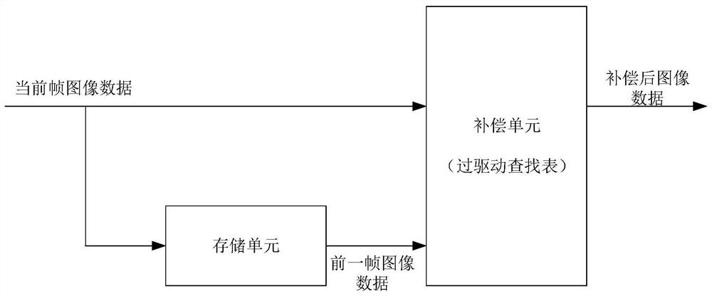
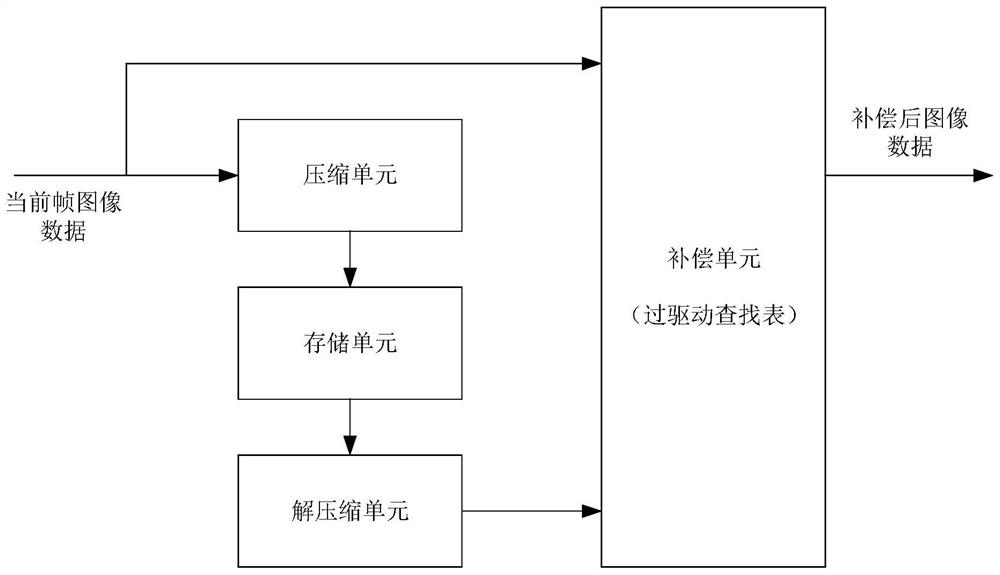

Image

  • Display driving method and device
  • Display driving method and device
  • Display driving method and device

Examples


Embodiment Construction

[0060]Various exemplary embodiments, features, and aspects of the present disclosure will be described in detail below with reference to the drawings. The same reference signs in the drawings indicate elements with the same or similar functions. Although various aspects of the embodiments are shown in the drawings, unless otherwise noted, the drawings are not necessarily drawn to scale.

[0061]The dedicated word "exemplary" here means "serving as an example, embodiment, or illustration." Any embodiment described herein as "exemplary" need not be construed as being superior or better than other embodiments.

[0062]In addition, in order to better illustrate the present disclosure, numerous specific details are given in the following specific embodiments. Those skilled in the art should understand that without certain specific details, the present disclosure can also be implemented. In some instances, the methods, means, elements, and circuits well-known to those skilled in the art have no...


PUM


Abstract

The invention relates to a display driving method and device, and the method comprises the steps: carrying out the partitioning of to-be-displayed current frame image data, and obtaining a plurality of pieces of image data; performing line segment mapping on pixels in each piece of image data, and determining line segments corresponding to the pixels of each piece of image data and line segment parameters of the line segments, wherein the line segment parameters comprise line segment pixel values and line segment lengths, each line segment corresponds to L columns of pixels, and L represents the line segment length; acquiring line segment parameters of corresponding block image data in the previous frame image data, and determining compensation data by utilizing the current frame image data, the line segment parameters of each block image data of the current frame image data and the line segment parameters of the corresponding block image data in the previous frame image data; and updating the current frame image data by using the compensation data, and driving the display panel to display the updated current frame image data. Through adoption of the method and the device, the smear problem caused by long response time of the panel can be eliminated, and the display accuracy of the display panel is improved.

Description

Technical field[0001]The present disclosure relates to the field of display technology, and in particular to a display driving method and device.Background technique[0002]At present, flat-panel displays such as LCD, LED, and OLED have gradually replaced traditional displays such as CRT, and are widely used in various industries, becoming an indispensable component of most electronic devices (such as mobile phones, Pads, TVs, computers, etc.). The response time of the panel is an important factor to measure the characteristics and quality of various types of panels. When the response time is too long, it will cause the screen to have motion smear or blur. For example, when using a mobile phone to move up and down the screen, it is easy to observe motion smear at the edges of the content such as strips, text, icons, and GUI, which affects the display effect. Such asfigure 1 As shown, assuming that the picture data bit width is 8bit (the value range is 0~255), the pixel value (Gray Lev...

Claims


Application Information

Patent Timeline
Patent Type & Authority Applications(China)
IPC IPC(8): G09G3/20G09G3/32G09G3/3208G09G3/36
CPCG09G3/2074G09G3/32
Inventor 王永刚
Owner CHIPONE TECH BEIJINGCO LTD
Learn More