Mechanical and electrical product detection table

A technology of electromechanical products and testing tables, which is applied in the field of testing tables, can solve the problems of inconvenient handling and high testing tables, and achieve the effect of lifting labor and preventing falling

Inactive Publication Date: 2021-01-05
蚌埠弘皓机电有限公司
View PDF0 Cites 1 Cited by
  • Summary
  • Abstract
  • Description
  • Claims
  • Application Information

AI Technical Summary

Problems solved by technology

[0003] Before the motor leaves the factory, it is necessary to test the various indicators of the motor, and because some motors are heavy, and the testing platform is relatively high, it is very inconvenient to transport to the testing platform

Method used


Image

  • Mechanical and electrical product detection table
  • Mechanical and electrical product detection table
  • Mechanical and electrical product detection table

Examples


Embodiment 1

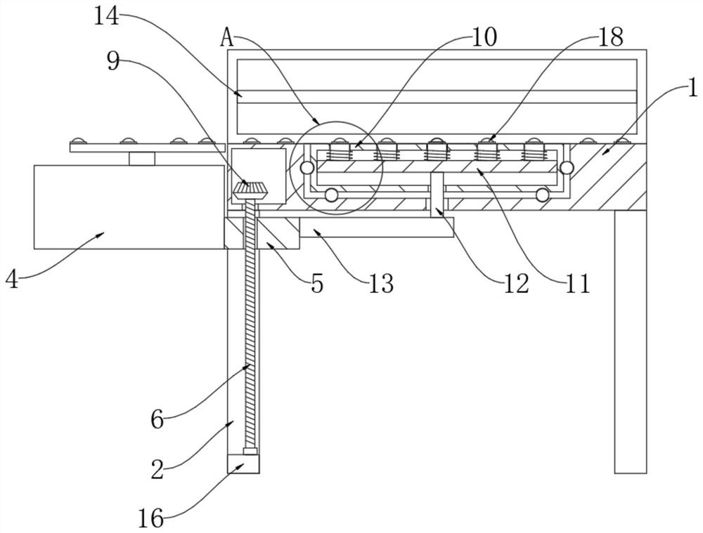
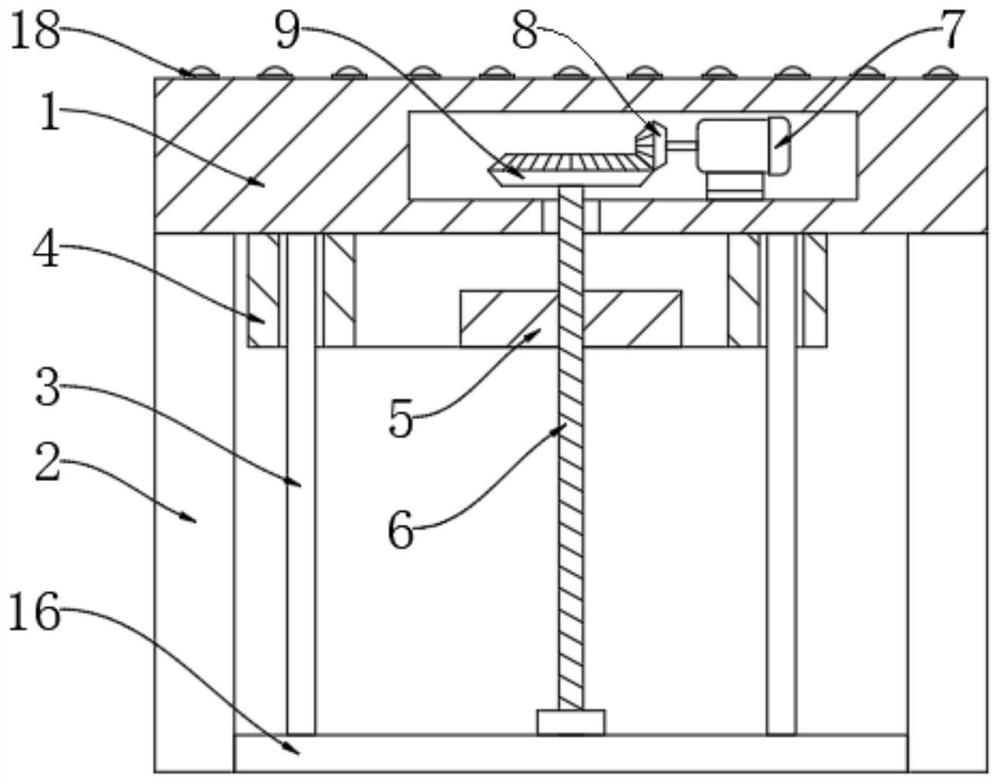
[0025] refer to Figure 1-4 , a testing platform for electromechanical products, including a workbench 1, support legs 2 are fixedly connected to the four corners of the lower surface of the workbench 1, a sliding column 3 is fixedly connected to the left edge of the lower surface of the workbench 1, and the sliding column 3 The surface is slidingly connected with a lifting plate 4, the side of the lifting plate 4 is fixedly connected with a connecting block 5, the upper surface of the connecting block 5 is provided with a threaded hole, and the inner wall of the threaded hole is threaded with a screw rod 6, and the two supporting legs 2 on the left The opposite surface is fixedly connected with a reinforced square rod 16, the bottom end of the sliding column 3 is fixedly connected with the upper surface of the reinforced square rod 16, and the bottom end of the screw rod 6 is rotatably connected with the upper surface of the reinforced square rod 16 through a bearing.

[0026...

Embodiment 2

[0033] refer to Figure 4-6, the inside of the lifting plate 4 is provided with an oil chamber 21, and the inside of the oil chamber 21 is provided with hydraulic oil, and the center of the upper surface of the lifting plate 4 is provided with a circular stepped groove extending to the inner top wall of the oil chamber 21, And the inner wall of the circular step groove is slidingly connected with a pressure column 22, the top of the pressure column 22 is fixedly connected with a pressure plate 23, the upper surface of the pressure plate 23 is provided with the same support ball 18 on the upper surface of the workbench 1, and the upper surface of the lifting plate 4 A U-shaped groove is provided, and the inner wall of the U-shaped groove is slidably connected with a U-shaped block 24, and the inner bottom wall of the U-shaped groove is provided with a circular hole extending to the inner wall of the oil chamber 21, and the inner wall of the circular hole is slidably connected wi...


PUM


Abstract

The invention discloses a mechanical and electrical product detection table, which comprises a workbench, wherein supporting legs are fixedly connected to the four corners of the lower surface of theworkbench, a sliding column is fixedly connected to the edge of the left side of the lower surface of the workbench, a lifting plate is slidably connected to the surface of the sliding column, a connecting block is fixedly connected to the side surface of the lifting plate, a threaded hole is formed in the upper surface of the connecting block, a screw is in threaded connection with the inner wallof the threaded hole, and a cavity is formed in the workbench. By arranging a servo motor, a small bevel gear, a large bevel gear, the screw, a jacking plate, a lifting plate and a material supporting ball, the servo motor is conveniently started to enable the screw to drive the lifting plate to ascend, so that the motor is lifted in a more labor-saving mode. Meanwhile, in the ascending process of the lifting plate, the jacking plate pushes the material supporting ball on the upper surface of the material supporting column out of a rotating disc, and in the descending process of the lifting plate, the material supporting ball on the upper surface of the material supporting column is hidden in the rotating disc, so that the motor can be fixed.

Description

technical field [0001] The invention relates to the technical field of testing platforms, in particular to a testing platform for electromechanical products. Background technique [0002] The motor is a kind of electromechanical product. The motor is an electromagnetic device that realizes the conversion or transmission of electric energy according to the law of electromagnetic induction. Now more and more mechanical products use motors. The appearance of motors has played a great role in the progress of human beings. [0003] Before the motor leaves the factory, various indicators of the motor need to be tested, and because some motors are heavy, and the testing platform is relatively high, it is very inconvenient to transport to the testing platform. [0004] The invention provides a testing platform for electromechanical products. Contents of the invention [0005] The purpose of the present invention is to solve the shortcomings in the prior art, and propose a testing...

Claims


Application Information

Patent Timeline
IPC IPC(8): G01R1/04G01R31/34
CPCG01R1/0408G01R31/34
Inventor 孙意克
Owner 蚌埠弘皓机电有限公司
Why Eureka
Try Eureka