Pressure transmitter based on ceramic pressure sensor
A technology of pressure sensor and transmitter, which is applied in the direction of measuring fluid pressure, instruments, measuring devices, etc. It can solve the problems of high cost, no consideration of O-ring limit, difficult processing, etc., and reduce production cost and management cost , Overcoming the high production cost and improving the effect of negative pressure resistance
- Summary
- Abstract
- Description
- Claims
- Application Information
AI Technical Summary
Problems solved by technology
Method used
Image
Examples
Embodiment 1
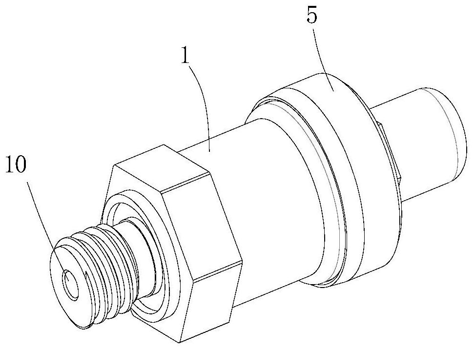
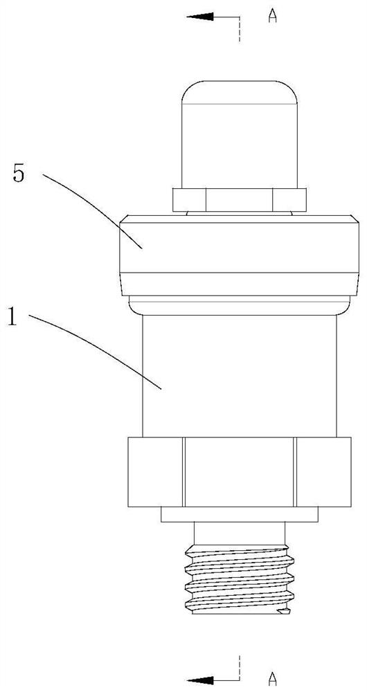
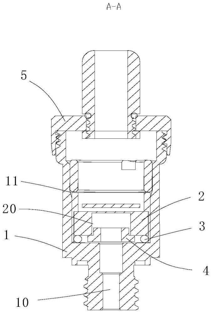
[0040] see figure 1 with figure 2 As shown, a pressure transmitter based on a ceramic pressure sensor includes a core body 1, one end of the core body 1 is provided with a medium inlet 10, and an installation cavity 11 communicated with the medium inlet 10, and the ceramic pressure sensor 2 is installed In the installation cavity 11, it is characterized in that a sealing ring 3 and a support member 4 to prevent the sealing ring from shrinking into the medium inlet are provided between the end surface of the ceramic pressure sensor 2 and the wall surface communicating with the installation cavity 11 and the medium inlet.
[0041] The present invention provides auxiliary support for the seal ring by adding a support member, avoiding the problem of seal failure caused by the seal ring being sucked inward, and the structure of the support member is simple, and the manufacturing cost is low. The approach of the limiting groove has obvious cost advantages, so that the present inve...
Embodiment 2
[0046] see figure 1 with figure 2 As shown, a pressure transmitter based on a ceramic pressure sensor includes a core body 1, one end of the core body 1 is provided with a medium inlet 10, and an installation cavity 11 communicated with the medium inlet 10, and the ceramic pressure sensor 2 is installed In the installation cavity 11, it is characterized in that a sealing ring 3 and a support member 4 to prevent the sealing ring from shrinking into the medium inlet are provided between the end surface of the ceramic pressure sensor 2 and the wall surface communicating with the installation cavity 11 and the medium inlet.
[0047] The support member 4 is an annular ring body 40, the hole in the middle of the ring body communicates with the medium inlet and the ceramic sensor hole, so that the medium enters the ceramic sensor, and the outer side of the ring body supports the inner ring of the sealing ring to prevent it from Problems with displacement under pressure.
[0048] F...
Embodiment 3
[0051] see figure 1 with figure 2As shown, a pressure transmitter based on a ceramic pressure sensor includes a core body 1, one end of the core body 1 is provided with a medium inlet 10, and an installation cavity 11 communicated with the medium inlet 10, and the ceramic pressure sensor 2 is installed In the installation cavity 11, it is characterized in that a sealing ring 3 and a support member 4 to prevent the sealing ring from shrinking into the medium inlet are provided between the end surface of the ceramic pressure sensor 2 and the wall surface communicating with the installation cavity 11 and the medium inlet.
[0052] The support member 4 is an annular ring body 40, the hole in the middle of the ring body communicates with the medium inlet and the ceramic sensor hole, so that the medium enters the ceramic sensor, and the outer side of the ring body supports the inner ring of the sealing ring to prevent it from Problems with displacement under pressure.
[0053] Th...
PUM
 Abstract
Description
Claims
Application Information
 - R&D
- Intellectual Property
- Life Sciences
- Materials
- Tech Scout
- Unparalleled Data Quality
- Higher Quality Content
- 60% Fewer Hallucinations
Browse by: Latest US Patents, China's latest patents, Technical Efficacy Thesaurus, Application Domain, Technology Topic, Popular Technical Reports.
© 2025 PatSnap. All rights reserved.Legal|Privacy policy|Modern Slavery Act Transparency Statement|Sitemap|About US| Contact US: help@patsnap.com


