A decorative panel auxiliary installation tool for building construction

A decorative plate and building construction technology, applied in the direction of construction and building structure, can solve the problems of low efficiency, uneven tile gap, uneven decorative surface, etc., and achieve the effect of convenient position alignment

Active Publication Date: 2021-05-18
张志广
View PDF5 Cites 0 Cited by
  • Summary
  • Abstract
  • Description
  • Claims
  • Application Information

AI Technical Summary

Problems solved by technology

At present, most of the tiles on the wall are manually operated. In the process of attaching the wall tiles, it is necessary to manually apply the cement slurry to the back of the wall tiles, and then lift the wall tiles and place them on the wall; this method is unskilled. Workers often make mistakes, resulting in inefficiency; at the same time, this method exists because the unfolded surface frame of the wall brick is large and the surface is smooth; manual handling is easy to cause the problem of inconvenient handling due to the smooth wall brick and large area; at the same time When laying tiles, it is necessary to ensure the flatness and accuracy of the tiles on the wall, and the gap between the tiles should be uniform. For the effect of wall decoration, most of the tiles have patterns on the decorative surface of the tiles. The decorative surface is uneven. When laying tiles manually, it is inevitable that the tiles are not straight, not accurate, and the gaps between the tiles are uneven, which seriously affects the overall aesthetics of the exterior wall.

Method used


Image

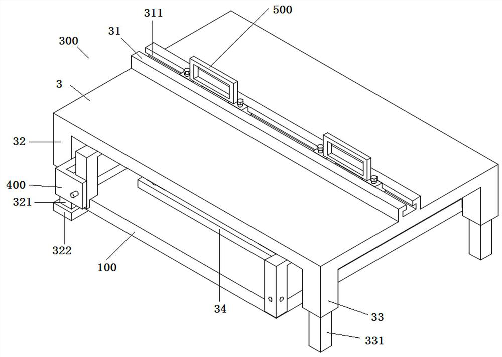
  • A decorative panel auxiliary installation tool for building construction
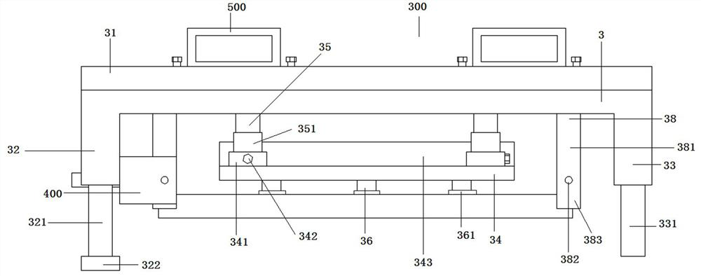
  • A decorative panel auxiliary installation tool for building construction
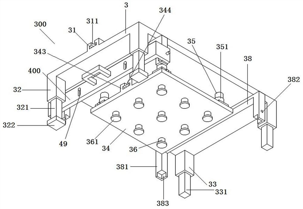
  • A decorative panel auxiliary installation tool for building construction

Examples


Embodiment Construction

[0028] The following will clearly and completely describe the technical solutions in the embodiments of the present invention with reference to the accompanying drawings in the embodiments of the present invention. Obviously, the described embodiments are only some, not all, embodiments of the present invention. Based on the embodiments of the present invention, all other embodiments obtained by persons of ordinary skill in the art without creative efforts fall within the protection scope of the present invention.

[0029] In describing the present invention, it is to be understood that the terms "opening", "upper", "lower", "thickness", "top", "middle", "length", "inner", "surrounding" etc. Indicating orientation or positional relationship is only for the convenience of describing the present invention and simplifying the description, and does not indicate or imply that the components or elements referred to must have a specific orientation, be constructed and operated in a sp...


PUM


Abstract

The invention discloses a tool for auxiliary installation of decorative panels for building construction, and relates to the technical field of building construction equipment. The invention includes a clamping mechanism for clamping and operating decorative panels. The clamping mechanism includes a base plate, and the back of the base plate At least one handle A is installed; the front of the base plate is connected to a movable plate through a number of telescopic cylinders, and a surface of the movable plate is provided with a number of fixed columns, the fixed column is a hollow pipe body, and the end of the fixed column is connected to a device for adsorption and decoration. The sucker A of the sheet material; two horizontal bars are arranged in parallel on the base plate at both ends of the movable plate, a positioning bar is arranged at both ends of the horizontal bar, and an L-shaped positioning block is arranged at the end of the positioning bar. Through the setting of the clamping mechanism, the present invention facilitates the clamping and moving operation of the decorative plate during the installation process of the decorative plate, and avoids the inconvenience and inconvenience of handling caused by the excessive weight, large unfolded area and smooth surface of the decorative plate during the bare-handed operation. Easy to slip problem.

Description

technical field [0001] The invention belongs to the technical field of building construction equipment, and in particular relates to a decorative plate auxiliary installation tool for building construction. Background technique [0002] Ceramic tiles play an important role in the beautification of the interior in the decoration of houses. According to the decoration position, ceramic tiles can be roughly divided into floor tiles and wall tiles. At present, most of the tiles on the wall are manually operated. In the process of attaching the wall tiles, it is necessary to manually apply the cement slurry to the back of the wall tiles, and then lift the wall tiles and place them on the wall; this method is unskilled. Workers often make mistakes, resulting in inefficiency; at the same time, this method exists because the unfolded surface frame of the wall brick is large and the surface is smooth; manual handling is easy to cause the problem of inconvenient handling due to the sm...

Claims


Application Information

Patent Timeline
Patent Type & Authority Patents(China)
IPC IPC(8): E04F21/18
CPCE04F21/1894
Inventor 张志广刘廷志张立
Owner 张志广
Why Eureka
Try Eureka