Wing applied to tilting wing aircraft

A technology for tilting wings and wings, applied in the field of wings, can solve problems such as difficulty in aircraft manipulation

Inactive Publication Date: 2021-01-05
CHINA HELICOPTER RES & DEV INST
View PDF11 Cites 4 Cited by
  • Summary
  • Abstract
  • Description
  • Claims
  • Application Information

AI Technical Summary

Problems solved by technology

[0004] Existing tilting-wing aircraft generally choose to use wings with relatively small aspect ratios to reduce the sensitivity of the wings to the angle of attack. By increasing the conversion flight height and speeding up the tilting process, the influence of lift loss of control is reduced. The conversion method will put more stringent conditions on the conversion process, and the aircraft will also enter a stage of difficult maneuvering for a short time, which greatly increases the unreliability of the flying signal during the deceleration phase.

Method used


Image

  • Wing applied to tilting wing aircraft
  • Wing applied to tilting wing aircraft
  • Wing applied to tilting wing aircraft

Examples


Embodiment Construction

[0025] The following will clearly and completely describe the technical solutions in the embodiments of the present invention in conjunction with the accompanying drawings in the embodiments of the present invention. Obviously, the described embodiments are only some of the embodiments of the present invention, not all of them. Based on the embodiments of the present invention, all other embodiments obtained by persons of ordinary skill in the art without making creative efforts belong to the protection scope of the present invention.

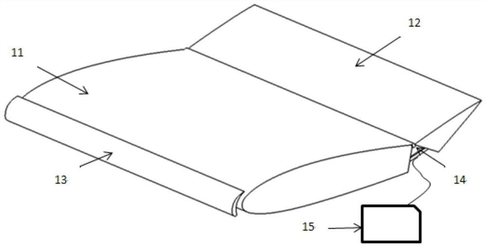
[0026] A wing design structure applied to a tilting wing aircraft such as figure 1 As shown, it is mainly divided into a wing main body 11, a wing trailing edge aerodynamic device 12, and a wing leading edge aerodynamic device 13. Wherein the wing trailing edge aerodynamic device 12 is fixed on the rear edge of the wing main body 11 through a rotatable connection mechanism 14, the wing leading edge aerodynamic device 13 is fixed on the wing lea...


PUM


Abstract

The invention belongs to the technical field of vertical / short-distance take-off and landing aircrafts, and particularly relates to a wing applied to a tilting wing aircraft. The wing mainly comprisesan aerofoil main body, an aerofoil trailing edge pneumatic device and an aerofoil leading edge pneumatic device. Wherein the wing trailing edge pneumatic device is fixed to the trailing edge of the wing body through a rotatable connecting mechanism, the wing leading edge pneumatic device is fixed to the wing leading edge, and the control device located in the aircraft can automatically set the proper angle of the trailing edge pneumatic device according to the attack angle of the wing. By arranging the front and rear edge pneumatic devices for the wing, the influence of the attack angle on the lifting force of the wing is artificially reduced, and the attack angle of the wing caused by stall is greatly delayed, so that the lifting force of the wing is controllable until the engine is erected to reach a high enough angle, and seamless connection from the wing to the engine can be realized through the control of the whole aircraft; and the controllability and the safety of the conversion stage are greatly improved.

Description

technical field [0001] The invention belongs to the technical field of vertical / short take-off and landing aircraft, and in particular relates to a wing applied to a tilting wing aircraft. Background technique [0002] Vertical take-off and landing aircraft can take off and land in a small space, and can perform complex tasks in a wide range of fields, from long-range high-speed to low-altitude and low-speed, and it is an important direction for the development of future aircraft. The tilting wing aircraft is one of the important layout forms, which has the advantages of simple tilting structure, more engines can be arranged, and propulsion engines can be used to provide hovering thrust. [0003] Due to the low flight speed (less than Mach 0.7) and the large number of engines (more than 2 sets) of the common tilting wing aircraft, it is difficult to use wings with large forward and backward sweep angles or wings with small aspect ratios. Use medium, large aspect ratio or ev...

Claims


Application Information

Patent Timeline
Patent Type & Authority Applications(China)
IPC IPC(8): B64C3/36B64C3/28
CPCB64C3/36B64C3/28
Inventor 罗骏
Owner CHINA HELICOPTER RES & DEV INST
Why Eureka
Try Eureka