
Efficient cooling type carriage for logistics transportation

An efficient and logistics technology, applied in transportation and packaging, vehicle components, superstructure of trucks, etc., can solve the problems of poor air circulation, easy to generate agglomeration, hidden dangers, etc., and achieve the effect of avoiding spontaneous combustion

Pending Publication Date: 2021-01-05
杨长建
View PDF0 Cites 0 Cited by
  • Summary
  • Abstract
  • Description
  • Claims
  • Application Information

AI Technical Summary

Problems solved by technology

[0003] The goods in the compartment are intricate. When there are a lot of flammable and explosive materials in the compartment, due to the sealing and anti-theft of the compartment, the air inside is often not circulated. As a result, the heat inside is difficult to communicate with the outside world under the sunlight Heat exchange is easy to generate accumulation, which will lead to spontaneous combustion of flammable materials in the compartment. The occurrence of spontaneous combustion has a great safety hazard and seriously affects normal traffic safety. Therefore, how to solve this problem is what we need to consider of

Method used


Image

  • Efficient cooling type carriage for logistics transportation
  • Efficient cooling type carriage for logistics transportation
  • Efficient cooling type carriage for logistics transportation

Examples


Embodiment 1

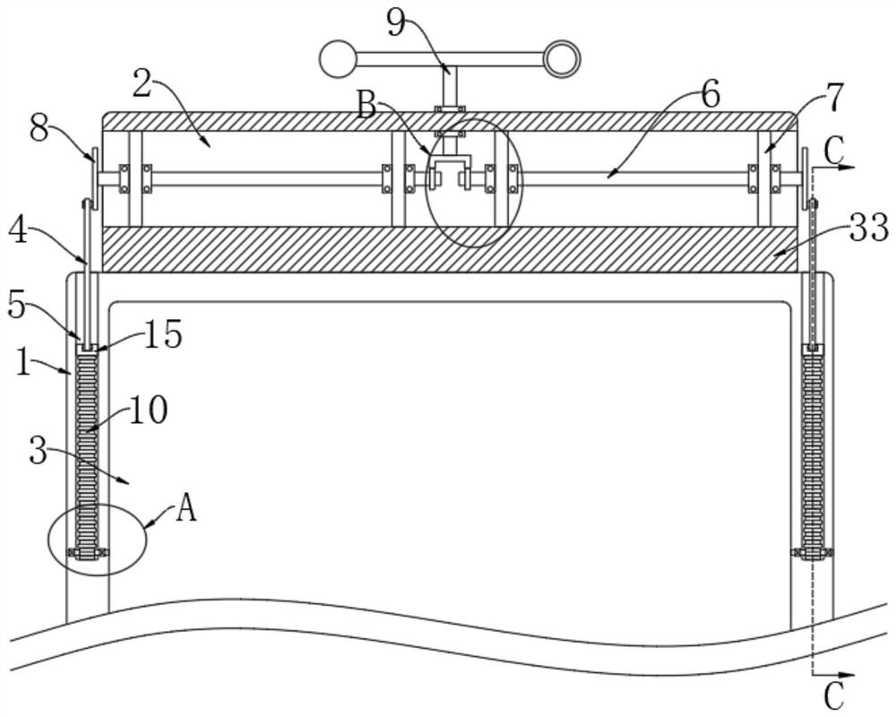
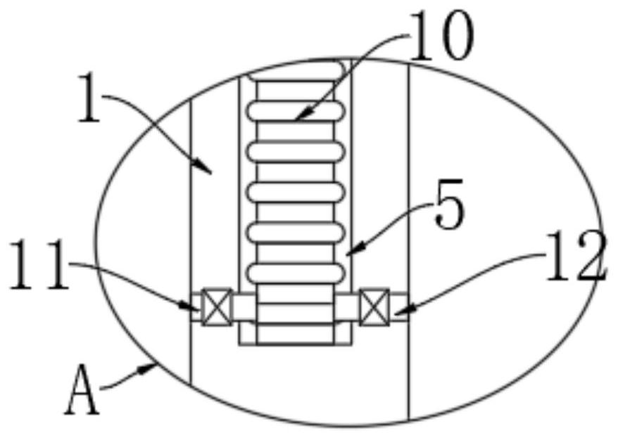
[0025] refer to Figure 1-4 , a high-efficiency cooling compartment for logistics transportation, including a compartment body 1 and an installation bar 33, the installation bar 33 is fixedly connected to the upper end of the compartment body 1, a storage room 3 is provided in the compartment body 1, and a through-hole is installed on the installation bar 33. slot 2;

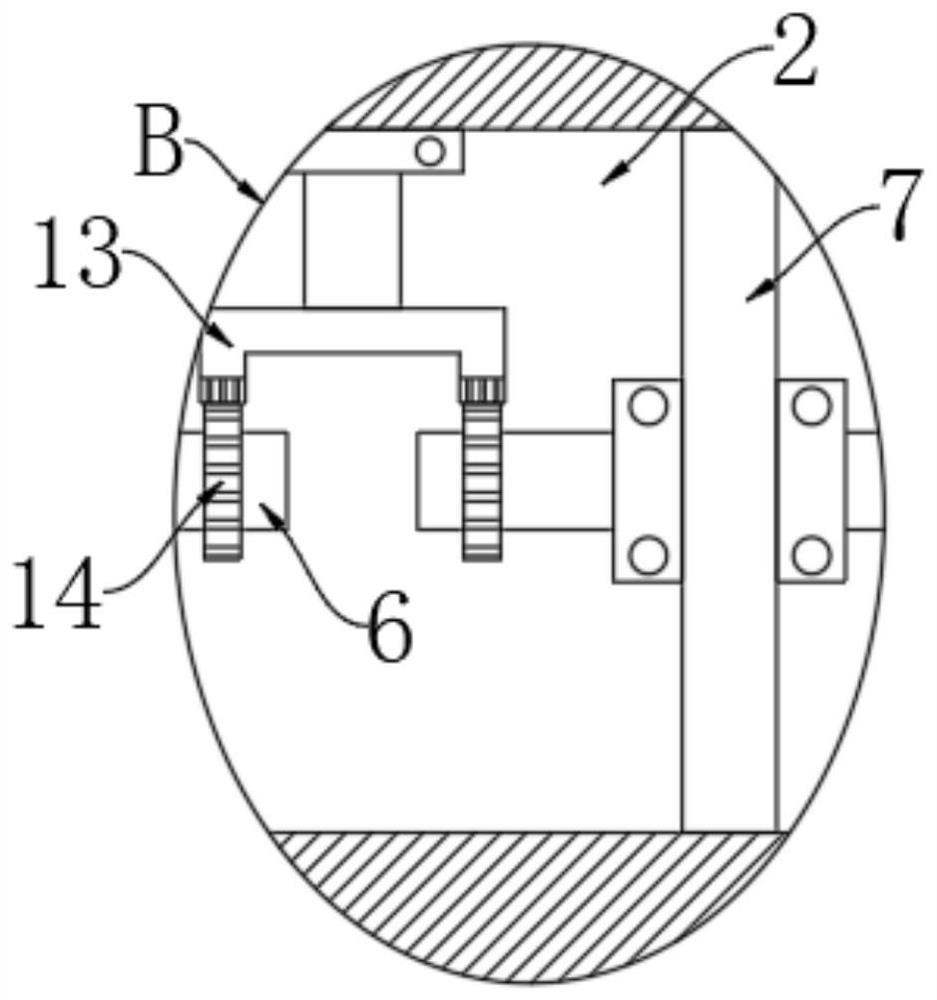
[0026] The trigger module, the trigger module includes the wind cup 9 installed on the upper end of the installation bar 33, the rotating shaft of the wind cup 9 extends into the through groove 2 and is fixedly connected with the crown gear 13;

[0027] The transmission module, the transmission module includes four mounting plates 7 vertically arranged in the through groove 2, the upper and lower ends of each mounting plate 7 are fixedly connected with the inner wall of the through groove 2, and between every two matching mounting plates 7 Both are rotatably connected with a rotating rod 6, and the opposite end...

Embodiment 2

[0033] refer to Figure 5 The difference between this embodiment and Embodiment 1 is that the middle parts of the two rotating rods 6 are provided with a threaded layer, and the threaded layer is a threaded layer similar to a reciprocating screw rod, so that the unidirectional rotation of the rotating rod 6 can drive the first The left and right movement of the magnetic block 17, the threaded layer parts of the two rotating rods 6 are all screwed with the first magnetic block 17, and the lower end of each first magnetic block 17 is all slidably connected with the inner bottom of the through groove 2, and the inner bottom of the mounting bar 33 Two transverse cavities 19 are symmetrically provided, and second magnetic blocks 18 for sliding left and right are arranged in the two transverse cavities 19, and the two second magnetic blocks 18 are all connected to the adjacent surfaces of the corresponding first magnetic blocks 17. Opposites attract each other, the two sides of the ...

Embodiment 3

[0036] refer to Figure 6-7 The difference between this embodiment and Embodiment 2 is that a trigger chamber 23 is provided in the box body 1, and two first pistons 25 sliding left and right are arranged in the trigger chamber 23, and the trigger chamber 23 is located between the two first pistons 25. The space between is filled with carbon disulfide solution, the second air bag 24 is arranged between the two first pistons 25, and the trigger chamber 23 is located at the opposite side space of the two first pistons 25, and the connection port 31 communicating with the storage chamber 3 is provided. , the upper end of the car body 1 is symmetrically provided with two vertical grooves 26, and the two vertical grooves 26 are respectively located on both sides of the trigger chamber 23, and the second piston 27 for sliding up and down is arranged in the two vertical grooves 26, and the two vertical grooves 26 The inside of the groove 26 is provided with a wedge-shaped block 28 fo...


PUM


Abstract

The invention provides an efficient cooling type carriage for logistics transportation. The carriage comprises a carriage body and a mounting strip, the mounting strip is fixedly connected with the upper end of the carriage body, a storage chamber is formed in the carriage body, and a through groove is formed in the mounting strip in a penetrating mode; the carriage further comprises a triggeringmodule which comprises a wind cup mounted at the upper end of the mounting strip, and a rotating shaft of the wind cup extends into the through groove and is fixedly connected with a crown gear; the carriage further comprises a transmission module which comprises four mounting plates vertically arranged in the through groove, the upper end and the lower end of each mounting plate are fixedly connected with the inner wall of the through groove, and a rotating rod is rotatably connected between every two matched mounting plates. The carriage is provided with active air exchange modules, the airexchange modules inside and outside the carriage are operated by utilizing wind energy in the running process of a vehicle, so that the situation that spontaneous combustion occurs due to heat accumulation inside the carriage is avoided, meanwhile, when the temperature is high, the outer wall of the carriage can be subjected to water spraying treatment, and the heat dissipation effect is better.

Description

technical field [0001] The invention relates to the field of logistics transportation, in particular to a high-efficiency cooling compartment for logistics transportation. Background technique [0002] Logistics transportation technology mainly includes two categories: transportation facilities and transportation operations. The former belongs to the hard technology of transportation, and the latter belongs to the soft technology of transportation. With the rapid development of the logistics system, large trucks are usually used for transportation between logistics outlets in large cities. Carry out transportation, and in the process of logistics transportation for present large truck, there are following problems: [0003] The goods in the compartment are intricate. When there are a lot of flammable and explosive materials in the compartment, due to the sealing and anti-theft of the compartment, the air inside is often not circulated. As a result, the heat inside is difficu...

Claims


Application Information

Patent Timeline
Patent Type & Authority Applications(China)
IPC IPC(8): B62D33/04B60H1/24B60H1/32
CPCB60H1/24B60H1/3202B62D33/04
Inventor 杨长建
Owner 杨长建
Learn More