
Turnover automatic clamp

A fixture and automatic technology, applied in the direction of clamping, manufacturing tools, support, etc., can solve the problems of inflexibility and single clamping method

Inactive Publication Date: 2021-01-05
左健康
View PDF8 Cites 0 Cited by
  • Summary
  • Abstract
  • Description
  • Claims
  • Application Information

AI Technical Summary

Problems solved by technology

[0003] The technical problem to be solved by the present invention is to provide a reversible automatic clamp, which solves the problem of single and inflexible clamping methods

Method used


Image

  • Turnover automatic clamp
  • Turnover automatic clamp
  • Turnover automatic clamp

Examples


Embodiment Construction

[0018] Combine below Figure 1-7 The present invention is described in detail, wherein, for the convenience of description, the orientations mentioned below are defined as follows: figure 1 The up, down, left, right, front and back directions of the projection relationship itself are the same.

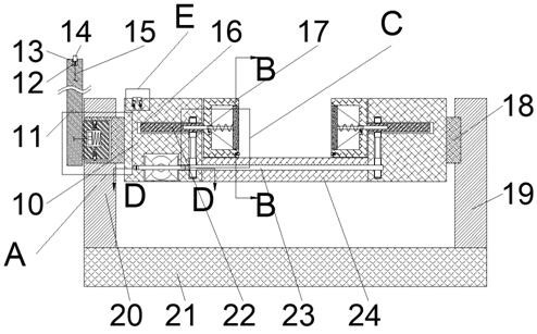
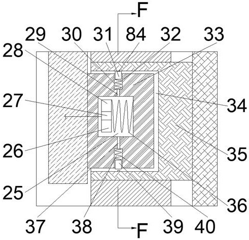
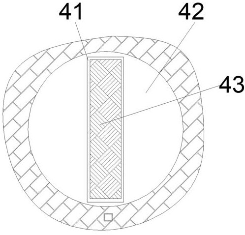
[0019] combined with Figure 1-7The reversible automatic fixture includes a base 21, the upper end of the base 21 is fixedly connected with a left support 20, and the upper end of the base 21 is fixedly connected with a right support on the right side of the left support 20. body 19, the left support body 20 is rotationally connected with a drive shaft 35 extending rightward through the left support body 20 to the right side of the left support body 20, and the drive shaft 35 is provided with a left opening A driving chamber 34, the driving chamber 34 is rotationally connected with a driving block 33, the driving block 33 is provided with a switching magnet chamber 25, and the upper ...


PUM


Abstract

The invention discloses a turnover automatic clamp. The turnover automatic clamp comprises a base, wherein a left supporting body is fixedly connected to the upper end face of the base; a right supporting body located at the right side of the left supporting body is fixedly connected to the upper end face of the base; a driving rotating shaft extending rightwards to penetrate through the left supporting body to the right side of the left supporting body is connected into the left supporting body in a running fit mode; a driving cavity with a leftward opening is arranged in the driving rotatingshaft; a driving block is connected into the driving cavity in a rotating fit mode; a switching magnet cavity is arranged in the driving block; clamping of the part is achieved by controlling left-right sliding of a moving shaft, controlling forward and reverse rotation of a spline shaft and pushing a threaded rod to do left-right reciprocating motion; when a curved surface part appears, a baffleis pushed, so that the curved surface is matched with a conical cavity, stable clamping of curved surface part is completed, and meanwhile, by controlling reciprocating swing of a rocker and switching of clamping blocks, one-way driving of the rocker is achieved, overturning of an overturning body is controlled, and machining of the part at all angles is achieved.

Description

technical field [0001] The invention relates to the technical field of clamps, in particular to a reversible automatic clamp. Background technique [0002] In the process of parts processing, the fixture is an indispensable tool. The structure of the fixture at this stage is simple, and most of them can only clamp the regular plane. The clamping force for some curved surface parts is not very ideal, so it often causes the parts to be in the process of processing. There are phenomena such as movement and falling off in the tool, which will cause damage to the tool and affect the production speed and quality. At the same time, the current fixture is not flexible enough, and the needle cannot realize the processing of some parts at special angles. Contents of the invention [0003] The technical problem to be solved by the present invention is to provide a reversible automatic clamp, which solves the problem of single and inflexible clamping methods. [0004] The present...

Claims


Application Information

Patent Timeline
Patent Type & Authority Applications(China)
IPC IPC(8): B23Q3/06B23Q7/00
CPCB23Q3/06B23Q7/00
Inventor 左健康
Owner 左健康
Learn More