Low-noise atomization cup convenient for dosing and air intake

A low-noise, atomizing cup technology, applied in the field of medical nebulizers, can solve the problems of reduced air intake, reduced treatment effect, patient anxiety, rejection, panic, etc., to achieve good noise reduction effect, reliable positioning, and increased air intake Effect

Pending Publication Date: 2021-01-05
JIANGSU YUYUE MEDICAL EQUIP&SUPPLY CO LTD +4
View PDF1 Cites 3 Cited by
  • Summary
  • Abstract
  • Description
  • Claims
  • Application Information

AI Technical Summary

Problems solved by technology

[0004] During the nebulization treatment, the patient inhales the aerosol through the inhalation mask or mouthpiece connected to the mist outlet of the nebulization cup. The distance between the nebulization cup and the patient is very close, so the gas-liquid in the nebulization cup The noise generated by the collision with the collision surface will have a certain impact on the patient's emotions. In severe cases, it may cause anxiety, rejection, and panic in the patient. Especially when used by children, the impact of noise on the therapeutic effect is more obvious.
[0005] Existing atomization cup technology, such as the patent "detachable noise reduction atomization cup" with application number CN201420479998.3, discloses an atomization cup capable of reducing noise. The cup cover of the atomization cup is equipped with The adjustment hole can control the noise by controlling the size of the adjustment hole while the air is entering, but when the noise is reduced, the air intake is also reduced, which will affect the amount of mist output from the atomization cup, resulting in a reduction in the therapeutic effect; and the mist The chemical cup needs to be opened to add medicine, which is not very convenient to use

Method used


Image

  • Low-noise atomization cup convenient for dosing and air intake
  • Low-noise atomization cup convenient for dosing and air intake
  • Low-noise atomization cup convenient for dosing and air intake

Examples


Embodiment 1

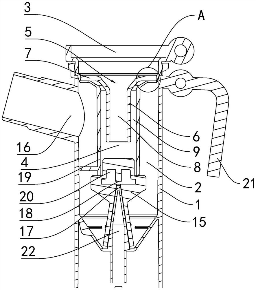
[0061] Embodiment one: see attached figure 1 to attach Figure 4 , and attached Figure 11 to attach Figure 13 , a low-noise atomizing cup convenient for dosing and air intake, the atomizing cup includes a cup shell 1, an inner cup 19 and a cup core 15;

[0062] as attached figure 1 And attached Figure 13 As shown, the cup shell 1 has a chamber 2, the upper end of the cup shell 1 is an opening 3 open upward, and the side wall of the cup shell 1 is provided with a mist outlet connecting the interior of the chamber 2 and the exterior of the chamber 2 16. There is also a handle 21 on the side wall of the cup shell 1. The bottom of the cup shell is provided with an air injection hole 22 whose inner diameter gradually decreases from bottom to top. The air injection hole 22 extends out of the cavity 2 and is connected with compressed air. It is conical, and the tip of the cone extends into the cavity 2 to form a jet port 17, and the jet port 17 is arranged upward;

[0063] T...

Embodiment 2

[0072] Embodiment two: see attached Figure 5 to attach Figure 7 , the difference between embodiment two and embodiment one is:

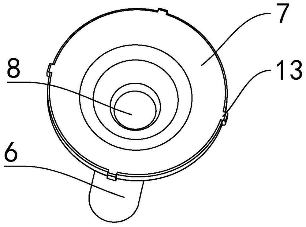
[0073] The muffler cavity 9 is provided with a spiral rib 10 surrounding the outer wall of the conduit part 6, and the support part 7 is provided with an air inlet 12 through its ring, and one end of the air inlet is connected to the outside of the cup shell 1, and the other end is connected to the outside of the cup shell 1. communicate with the chamber 2 through the sound-absorbing chamber 9;

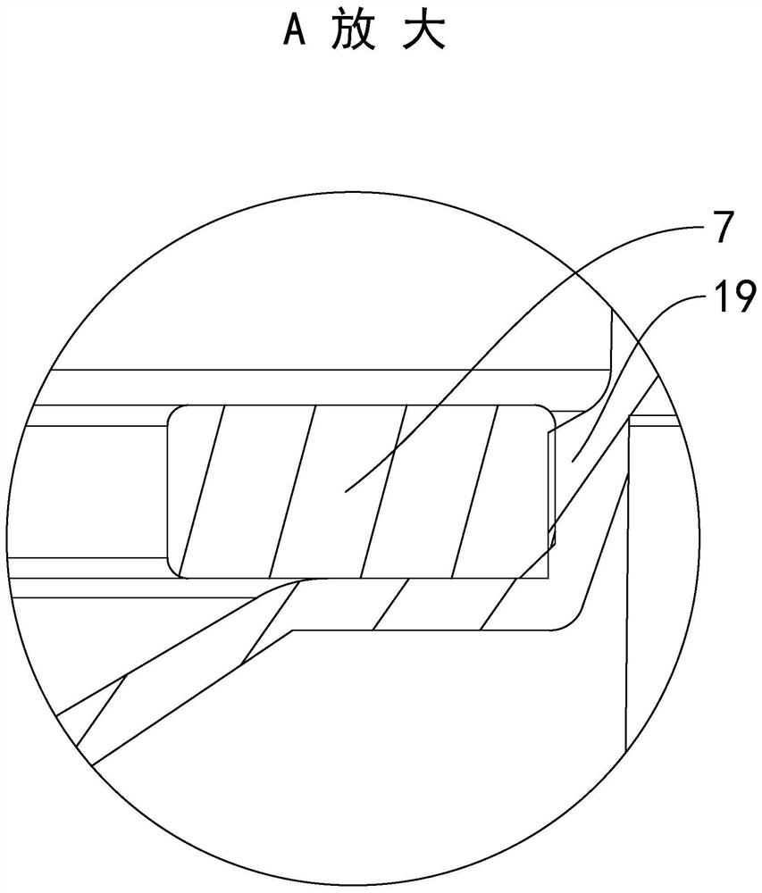
[0074] In the installed state, viewed along the up and down direction, the width of the spiral rib 10 is equal to the cross-sectional ring width of the sound-absorbing chamber 9, so that the spiral rib 10 is set in the sound-absorbing chamber 9, and the noise will be reduced when it propagates in the sound-absorbing chamber 9 Blocked by the spiral ribs 10, the noise is further weakened, and the support portion 7 can open air intake holes 12 to further in...

Embodiment 3

[0076] Embodiment three: see attached Figure 8 to attach Figure 10 , the difference between embodiment three and embodiment one is:

[0077] A plurality of sieve holes 11 are penetrated in the pipe wall of the conduit part 6 along the vertical direction, and the plurality of sieve holes 11 are arranged around the pipe 8 and separated between the conduit part 6 and the channel 4 to form the muffler cavity 9 ;

[0078] In the installed state, there is a clearance fit between the pipe wall of the conduit part 6 and the inner wall of the passage 4, and the gap width of the gap is much smaller than the ring section ring width of the muffler chamber 9 in Embodiment 1, so that The muffler chamber 9 formed by the screen holes 11 in the third embodiment replaces the muffler chamber 9 of the annular cavity structure, and the structure arranged around the pipe 8 by the screen holes 11 is similar to a honeycomb structure, and its narrow cross-section can reflect noise and weaken its e...


PUM


Abstract

Disclosed is a low-noise atomization cup convenient for dosing and air intake. A containing cavity is formed in a cup shell of the atomization cup; an opening is formed in the cup shell; a silencing device is positioned and installed in the opening, a supporting part of the silencing device is positioned in the opening in the installation state, and a guide pipe part of the silencing device stretches into a channel in the opening position; a pipeline with the length-diameter ratio of 1 or above penetrates through the guide pipe part of the atomization cup; the pipeline communicates with the containing cavity and the outer portion of the cup shell; a circle of silencing containing cavity is formed between the guide pipe part and the inner wall of the channel, and the silencing containing cavity can block and weaken noise; when the atomization cup works, part of noise in the containing cavity is transmitted out of the pipeline of the guide pipe part, and the other noise enters the silencing containing cavity; noise in the pipeline and the silencing containing cavity can be reflected back and forth to lose a part of energy and is weakened, the noise in the pipeline and the silencing containing cavity counteracts vibration generated by the guide pipe part, and the noise is further weakened; and therefore, the pipeline is matched with the silencing containing cavity, and a relatively good silencing effect is achieved.

Description

technical field [0001] The invention relates to the field of medical nebulizers, in particular to a jet-type atomizing cup used in nebulization inhalation treatment. Background technique [0002] Nebulization inhalation therapy is a treatment method for respiratory diseases such as asthma, bronchitis and pharyngitis, among which jet nebulization cup is the mainstream equipment for nebulization inhalation treatment. [0003] The main function of the atomization cup is to atomize the liquid medicine in the cup for inhalation by the patient. The atomization process uses the Venturi principle to send external compressed air (or oxygen) into the atomization cup through the pipeline, and then from the mist A jet hole with a narrow cross-section inside the chemical cup ejects at high speed and hits the collision surface. The high-speed airflow generates a negative pressure area during the impact, so that the liquid medicine is sucked into the high-speed airflow under the action of ...

Claims


Application Information

Patent Timeline
IPC IPC(8): A61M15/00
CPCA61M15/0086A61M2205/42A61M15/0001
Inventor 余先臣张佳王凯马骏赵帅
Owner JIANGSU YUYUE MEDICAL EQUIP&SUPPLY CO LTD
Why Eureka
Try Eureka