
Non-return valve, in particular for a refrigeration or heat circuit

A technology of heating circuit and check valve, which is applied in the direction of control valves, refrigerators, refrigeration components, etc., can solve the problems of increased leakage rate, etc., and achieve the effects of improved reset force, fast closing process, simple layout and guidance

Active Publication Date: 2021-01-01
OTTO EGELHOF GMBH & CO KG
View PDF10 Cites 2 Cited by
  • Summary
  • Abstract
  • Description
  • Claims
  • Application Information

AI Technical Summary

Problems solved by technology

Every interface or connection point in the refrigeration circuit can lead to an increased leak rate

Method used


Image

  • Non-return valve, in particular for a refrigeration or heat circuit
  • Non-return valve, in particular for a refrigeration or heat circuit
  • Non-return valve, in particular for a refrigeration or heat circuit

Examples


Embodiment Construction

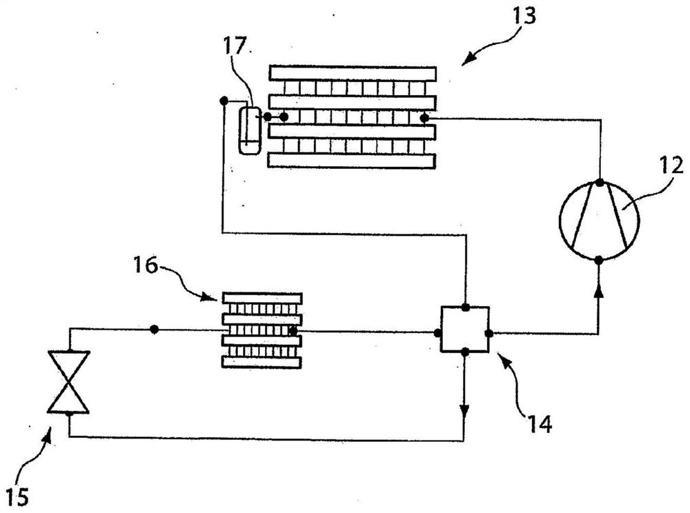
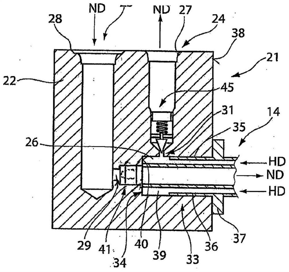
[0053] figure 1 In particular, the conventional structure of a cooling or heating circuit 11 of an air-conditioning system, which is preferably used in a motor vehicle, is shown. Refrigerant is compressed in compressor 12 . The refrigerant can be, for example, R134A, R1234yf or CO 2 . The compressed refrigerant is supplied to the condenser 13, wherein heat exchange occurs between the compressed refrigerant and the surrounding environment in order to cool the refrigerant. An accumulator 17 or collector can be provided downstream of the condenser 13 in order to separate the refrigerant in the gaseous and liquid phases and simultaneously collect the liquid refrigerant. Refrigerant leaving the condenser 13 or the accumulator 17 reaches the internal heat exchanger 14 . An expansion valve 15 is arranged between the internal heat exchanger 14 and the heat exchanger 16 . The mass flow of the cooling or heating circuit 11 is regulated via the expansion valve 15 as a function of th...


PUM


Abstract

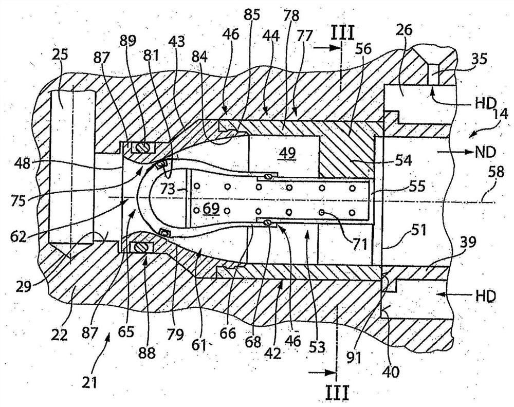
The invention relates to a non-return valve, in particular for a refrigeration or heat circuit, which valve can be inserted into a connection opening (26, 27, 28, 29) of a connection device (21) or ofa pipe (39) and comprises: - a one-part or multi-part housing (42) which comprises at least one main housing (44), a feed opening (48) being provided on the inlet side and a discharge opening (51) being provided on the outlet side of the main housing (44), the feed opening and the discharge opening being interconnected by a flow channel (49); - a guide element (53) which is provided on the main housing (44) and by means of which a valve closing element (61) is guided slidably relative to the main housing (44), the valve closing element (61) being arranged in a starting position (42) by meansof an energy accumulator (71) and the valve closing element (61) being slidable toward the discharge opening (51) against an actuating force of the energy accumulator (71) in order to be transferred into a working position (63), and the energy accumulator (71) being provided between the valve closing element (75) and the main housing (44), the guide element (53) of the main housing (44) having atleast one through-hole (57) and at least one guide rod (59) being guided in said at least one through-hole (57), which rod at least extends from the valve closing element (61) through the at least onethrough-hole (57) and is secured against release from the through-hole (57), or the guide element (53) being designed as a sleeve (54) having a bottom (55), which is associated with the discharge opening (51), and the valve closing element (61) having a guide portion (66) which acts on the sleeve (54).

Description

technical field [0001] The invention relates to a non-return valve which can be used in particular in refrigeration or heating circuits. Background technique [0002] A non-return valve is known from JP 2001-280 521 A, which consists of a two-part housing. A flow channel is provided in the housing, which is closed in the initial position by means of a valve closure. The valve closure is guided in the opening of the base housing by an axial guide rod. Between the base housing and the valve closure, a force storage element is arranged coaxially to the guide rod, which arranges the valve closure in the initial position. In this initial position, the valve closure closes the flow channel or the inlet opening on the valve housing, which is connected to the base housing. [0003] Similar arrangements are known from AU 2013 297717 B2, DE 201 18 810 U1 and US 4 955 407 A. [0004] Such non-return valves are used to ensure the operating state and to control the direction of flow ...

Claims


Application Information

Patent Timeline
Patent Type & Authority Applications(China)
IPC IPC(8): F16K1/36F16K1/42F16K15/06F16K27/02F25B40/00F28F9/02F28F27/02F28D7/10
CPCF16K1/36F16K1/42F16K15/063F16K27/0209F28F27/00F25B2341/063
Inventor E·维勒斯A·奥韦德R·毛雷尔S·罗特U·赫尔穆特B·瓦格纳
Owner OTTO EGELHOF GMBH & CO KG
Learn More