Cable trench structure for slowing cable corrosion
A cable corrosion and cable trench technology, applied in the field of cable trench structure, can solve problems such as cable corrosion, achieve the effect of alleviating corrosion and avoiding the decline of dehumidification ability
- Summary
- Abstract
- Description
- Claims
- Application Information
AI Technical Summary
Problems solved by technology
Method used
Image
Examples
Embodiment 1
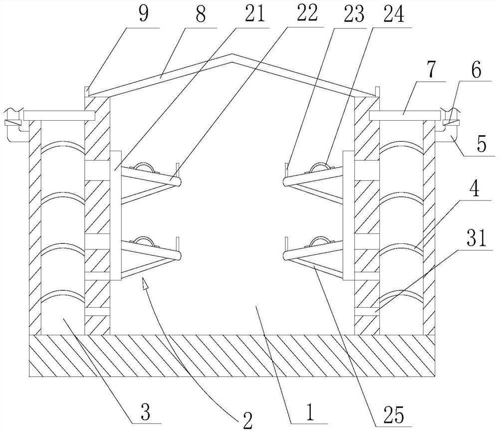
[0044] Such as figure 1 , figure 2 As shown, the cable trench structure that is beneficial to slow down cable corrosion includes a channel 1, the top of the channel 1 is provided with a top cover 8, and the inner wall of the channel 1 is provided with a cable support 2, and the cable support 2 includes A fixed plate 21, the fixed plate 21 is connected to the inner wall of the channel 1 by bolts, the fixed plate 21 is provided with a support plate 22, the side wall of the channel 1 is provided with an interlayer 3, and the inner side of the interlayer 3 The wall is provided with a number of ventilation holes 31 for connecting the channel 1 and the interlayer 3, the interlayer 3 is provided with a number of drying plates 4, the drying plates 4 are filled with desiccant, and the drying plates 4 are upward convex The desiccant is a bagged structure, the bag is made of ventilated fabric, the desiccant is packed into the bag, and then the bag is laid flat on the drying plate 4. Th...
Embodiment 2
[0046] Such as figure 1 , figure 2 As shown, the present embodiment is based on Embodiment 1. Several first humidity sensors are arranged in the interlayer 3, and several second humidity sensors are arranged in the channel 1, and a ventilation duct 5 communicating with the interlayer 3 is also included. The ventilation duct 5 is provided with a fan 6, and the fan 6 is used for deriving the airflow in the interlayer 3, and also includes a controller;
[0047]The first humidity sensor and the second humidity sensor are used to sense the humidity inside the interlayer 3 and the inside of the channel 1 in real time respectively, and transmit the sensed humidity signal to the controller;
[0048] The controller receives the humidity signal and makes an analysis to judge whether to open the fan 6;
[0049] After the fan 6 receives the instruction from the controller, it will automatically open and export the airflow in the interlayer 3;
[0050] It also includes a terminal, whic...
Embodiment 3
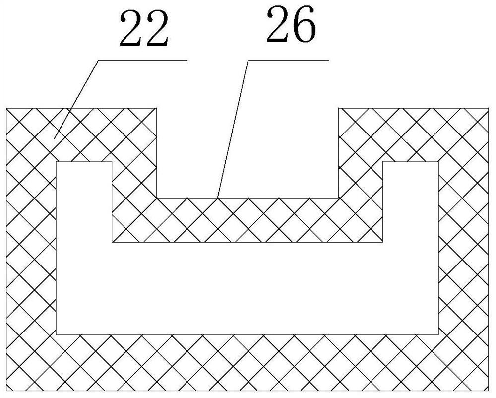
[0052] Such as figure 1 , figure 2 As shown, this embodiment is based on Embodiment 1, the support plate 22 is arranged obliquely, the high end of the support plate 22 is the end connected to the fixed plate 21, and the low end of the support plate 22 is provided with a baffle plate 23, so The support plate 22 is a hollow structure, and the side wall of the support plate 22 is provided with a number of through holes, and the fixed plate 21 is provided with communication holes for connecting the support plate 22 and the ventilation holes 31; the support plate 22 is Square structure, the upper end of the square structure is recessed downward to form a groove 26, the bottom of the baffle plate 23 is fixed on the lower end of the groove 26; a reinforcing plate is arranged between the bottom of the support plate 22 and the fixing plate 21 25.
PUM
 Abstract
Description
Claims
Application Information
 - R&D
- Intellectual Property
- Life Sciences
- Materials
- Tech Scout
- Unparalleled Data Quality
- Higher Quality Content
- 60% Fewer Hallucinations
Browse by: Latest US Patents, China's latest patents, Technical Efficacy Thesaurus, Application Domain, Technology Topic, Popular Technical Reports.
© 2025 PatSnap. All rights reserved.Legal|Privacy policy|Modern Slavery Act Transparency Statement|Sitemap|About US| Contact US: help@patsnap.com


