Sunshine-proof self-heat-dissipation bridge

A self-cooling, bridge technology, applied in electrical components and other directions, can solve the problem of difficult to effectively dissipate heat, and achieve a good cooling effect

Inactive Publication Date: 2021-01-01
徐玲
View PDF7 Cites 3 Cited by
  • Summary
  • Abstract
  • Description
  • Claims
  • Application Information

AI Technical Summary

Problems solved by technology

[0005] The purpose of the present invention is to solve the problem that most traditional bridges are difficult to effectively dissipate heat, and to provide a self-radiating bridge with high degree of automation

Method used


Image

  • Sunshine-proof self-heat-dissipation bridge
  • Sunshine-proof self-heat-dissipation bridge
  • Sunshine-proof self-heat-dissipation bridge

Examples


Embodiment 1

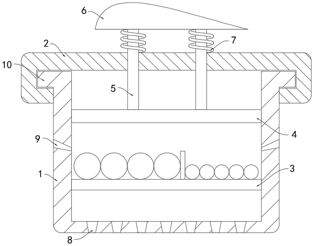
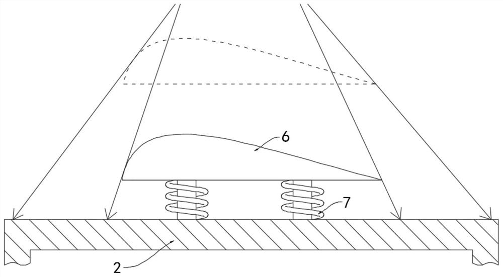
[0022] Such as Figure 1-2 As shown, a sun-proof self-radiating bridge includes a bracket groove 1. It is worth mentioning that the side walls on both sides of the bracket groove 1 extend outward to form a fixing strip 10, and the cross-section of the top cover 2 is C-shaped, which can strengthen the bracket. The connection between the slot 1 and the top cover, the upper end of the bracket slot 1 is detachably connected with the top cover 2 .

[0023] A horizontally arranged bearing plate 3 is fixedly connected to the bracket groove 1, and a horizontally arranged lifting plate 4 is arranged on the upper end of the bearing plate 3. The lifting plate 4 shown is slidingly connected to the inner side wall of the bracket groove 1, and the upper side wall of the lifting plate 4 is fixedly connected with a A plurality of connecting rods 5 are arranged vertically, and the other ends of the connecting rods 5 extend to the upper end of the top cover 2 and are fixedly connected with a wi...

Embodiment 2

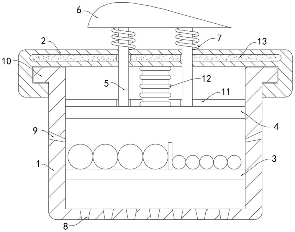
[0031] Such as image 3 As shown, the difference between the present embodiment and Embodiment 1 is that a horizontal storage bag 11 is fixedly connected to the upper side wall of the lifting plate 4, and a corrugated corrugated connection with the storage bag 11 is fixedly connected between the lifting plate 4 and the top cover 2. The tube 12, the storage bag 11 and the bellows 12 are all transparent and contain silver bromide powder inside.

[0032] It is worth mentioning that there is a storage chamber 13 inside the top cover 2, and the storage chamber 13 is filled with paraffin wax. When the paraffin wax is in a solid state, it is opaque, and after melting, it will liquefy into a transparent liquid. After melting, the light can be irradiated into the storage bag 11, that is, it will start when both the temperature and the light are met, which can effectively prevent the interference of other light.

[0033] In this embodiment, strong sunlight shines on the top cover 2, an...


PUM


Abstract

The invention belongs to the field of cable bridges, and particularly relates to a sunshine-proof self-heat-dissipation bridge which comprises a support groove, a top cover is detachably connected tothe upper end of the support groove, and a horizontally-arranged bearing plate is fixedly connected in the support groove, the sunshine-proof self-heat-dissipation bridge is characterized in that a horizontally-arranged lifting plate is arranged at the upper end of the bearing plate; and the lifting plate is slidably connected with the inner side wall of the support groove, a plurality of vertically-arranged connecting rods are fixedly connected to the upper side wall of the lifting plate, the other ends of the multiple connecting rods extend to the upper end of the top cover and are jointly and fixedly connected with a wing plate, and a plurality of memory springs are fixedly connected between the wing plate and the upper side wall of the top cover. A plurality of air outlet holes which are uniformly distributed are formed in the bottom surface of the bracket groove in a penetrating manner. By arranging the storage bag, the silver bromide in the storage bag can be rapidly decomposed to generate brown gas when meeting light, the brown gas can effectively prevent sunlight from irradiating the cable in the support groove, and the situation that the cable is irradiated by the sunlightto be aged in an accelerated mode is avoided.

Description

technical field [0001] The invention belongs to the field of cable bridges, in particular to a sunshine-proof self-radiating bridge. Background technique [0002] In the process of cable erection, various fixing equipment are often needed to fix it. The bridge is one of them. The cable bridge is composed of brackets, brackets and installation accessories. It is mainly divided into trough cable bridge and tray cable. Trays and stepped cable trays. [0003] Most of the traditional cable bridges are mainly composed of opaque bracket grooves and top covers. The cables are completely sealed inside the bridge. When the cable line fails, the entire top cover needs to be opened for inspection. It is set to be transparent, and the cable will be exposed to the sun in strong sunlight. It is easy to accelerate the aging of the cable sheath in the long run, and the cable is sealed in the bridge frame, which is not conducive to its own heat dissipation, and it is in a high environment fo...

Claims


Application Information

Patent Timeline
IPC IPC(8): H02G3/04H02G3/03
CPCH02G3/03H02G3/0406H02G3/0412H02G3/045
Inventor 徐玲曹钰坤
Owner 徐玲
Why Eureka
Try Eureka