Pressure detection control method for pipeline joint

A detection control and connection technology, which is applied in the field of pressure detection and control at pipeline connections, can solve problems such as the inability to detect pressure at pipeline connections, and achieve the effects of improving the scope of use and practicability, reducing waste, and avoiding pipeline leakage.

Inactive Publication Date: 2021-01-01
蒋奕阳
View PDF0 Cites 0 Cited by
  • Summary
  • Abstract
  • Description
  • Claims
  • Application Information

AI Technical Summary

Problems solved by technology

[0007] The purpose of the present invention is to provide a pressure detection and control method for pipeline joints to solve the problem that the traditional pressure detection devices for pipeline joints on the market cannot perform leak-proof work well during detection and cannot detect different pressures. The problem of pressure detection work at the pipe connection of the form

Method used


Image

  • Pressure detection control method for pipeline joint
  • Pressure detection control method for pipeline joint
  • Pressure detection control method for pipeline joint

Examples


Embodiment Construction

[0028] The following will clearly and completely describe the technical solutions in the embodiments of the present invention with reference to the accompanying drawings in the embodiments of the present invention. Obviously, the described embodiments are only some, not all, embodiments of the present invention. Based on the embodiments of the present invention, all other embodiments obtained by persons of ordinary skill in the art without making creative efforts belong to the protection scope of the present invention.

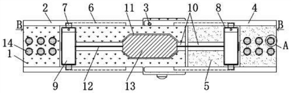
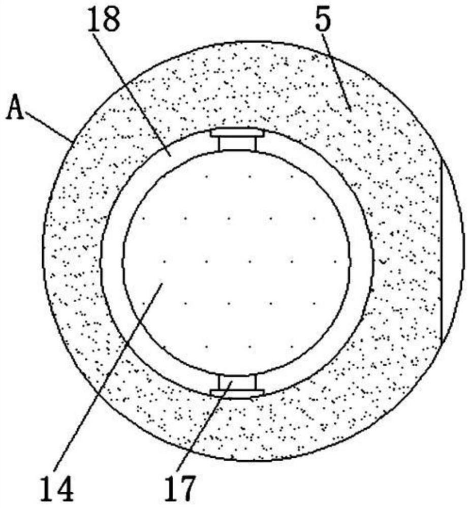
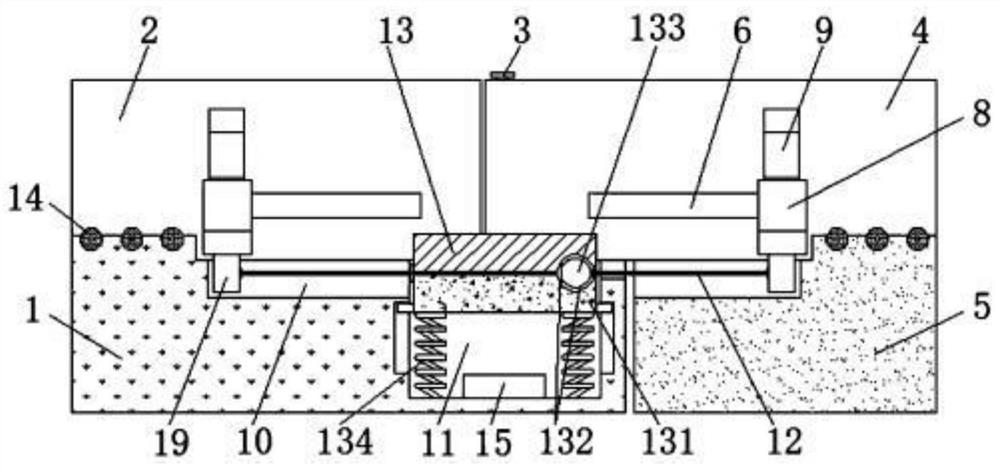
[0029] see Figure 1-7 , the present invention provides a technical solution: a method of pressure detection and control at a pipe joint, comprising a left placement plate 1, a left baffle plate 2, a connecting shaft 3, a right baffle plate 4, a right placement plate 5, a limit groove 6, Limiting block 7, lower hoop 8, upper hoop 9, chute 10, placement groove 11, connecting rope 12, detection upper plate 13, ball 14, pressure sensor 15, through groove 16, supp...


PUM


Abstract

The invention discloses a pressure detection control method for a pipeline joint. The detection control method is realized based on pressure detection equipment, and the pressure detection equipment comprises a left placing plate, left baffles, upper hoops, a pressure sensor, grooves and movable blocks; the front and rear side faces of the left placing plate are each fixedly provided with the leftbaffle; the upper side of the right end of the left placing plate is connected with right baffles through a connecting shaft, and a right placing plate is arranged on the right side of the left placing plate; the right baffles are installed on the front and rear side faces of the right placing plate correspondingly, and limiting grooves are formed in the inner side faces of the right baffles andthe left baffles correspondingly; sliding grooves are formed in the upper surfaces of the right placing plate and the left placing plate; the movable blocks are connected with the interiors of the sliding grooves in a clamped mode, and lower hoops are fixedly welded at the top ends of the movable blocks; and the upper hoops are movably connected with the upper portions of the lower hoops through shafts. Through arrangement of a detection upper plate, pipeline leakage can be avoided while the pressure is detected, and material waste is reduced.

Description

[0001] This application is a divisional application of a Chinese invention patent application with the application number 201911269955.6 filed on December 11, 2019, and the title of the invention is a leak-proof pipeline joint pressure detection device. technical field [0002] The invention relates to the technical field of detection, in particular to a pressure detection control method at a pipeline connection. Background technique [0003] As the name implies, detection is to detect various properties or characteristics of various items in order to better understand and protect various items. At present, it is necessary to perform pressure detection on the connection of pipelines in order to monitor the stability of the connection of pipelines in time. Conditions and pressure conditions, although there are many types of pressure detection devices for pipeline connections on the market, there are still some deficiencies, such as: [0004] 1. The traditional pressure detect...

Claims


Application Information

Patent Timeline
Patent Type & Authority Applications(China)
IPC IPC(8): F17D5/00F17D5/02
CPCF17D5/00F17D5/02
Inventor 蒋奕阳
Owner 蒋奕阳
Why Eureka
Try Eureka