A ring clamp synchronous fastening device
A technology of fastening device and ring clamp, which is applied in the direction of friction-clamped detachable fasteners, clutches, connecting components, etc., can solve problems such as poor installation accuracy of clamps, achieve low cost, avoid rotation displacement deviation, and structure Sophisticated Effects
- Summary
- Abstract
- Description
- Claims
- Application Information
AI Technical Summary
Problems solved by technology
Method used
Image
Examples
Embodiment 1
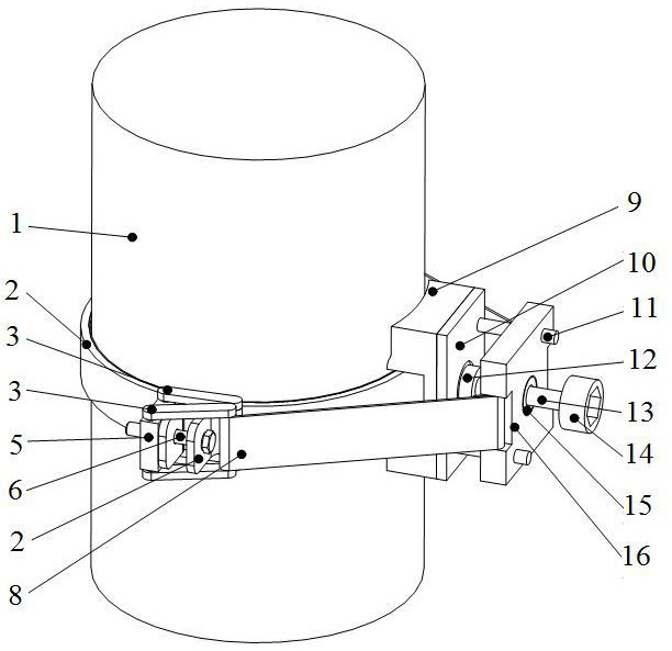
[0028] A ring clamp synchronous fastening device, such as figure 1 As shown, it includes two semicircular clamps 2 that cooperate with each other, buckles, bases, and linear motion devices. Buckles are respectively provided at the two ends of adjacent semicircular clamps 2, and bases are provided between adjacent buckles. The base is flexibly and tightly attached to the fastening part 1 , and a linear motion device is vertically arranged on the base, and both sides of the linear motion device are respectively connected to buckles through flexible belts 8 .
[0029] During the use of the present invention, the linear motion device drives the flexible belts 8 at both ends to reciprocate along a straight line to loosen or tighten the buckle, thereby realizing the fastening of the semicircular clamp 2 . Synchronous fastening of the ring clamp is realized by synchronously driving the linear motion of the flexible belts 8 on both sides of the linear motion device. The invention sol...
Embodiment 2
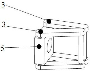
[0031] This embodiment is optimized on the basis of embodiment 1, such as figure 2 As shown, the buckle includes a spacer 5 and a lock 3, one side of the spacer 5 is provided with a profile that abuts against the semicircular clamp 2, and the two ends of the spacer 5 are respectively connected to the lock through a shaft. buckle 3, the other end of the lock buckle 3 is connected with the linear motion device through a flexible strap 8. The two ends of adjacent semicircular clamps 2 are respectively connected by fastening bolts 6 , and sliding holes are provided on the pads 5 corresponding to the fastening bolts 6 . The two ends of the spacer 5 are respectively provided with pin holes, and are connected with the latch 3 through a latch. The invention can realize the synchronous tightening of the ring clamp, avoid the rotation displacement deviation in the installation process of the ring clamp, and ensure the installation accuracy of the ring clamp.
[0032] Other parts of t...
Embodiment 3
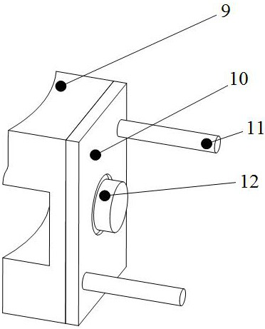
[0034] This embodiment is optimized on the basis of embodiment 1 or 2, as figure 1 , image 3 , Figure 4 As shown, the linear motion device includes a slider 16 and a screw 13, the screw 13 passes through the slider 16 and is connected to the base in rotation, and the slider 16 moves linearly along the length of the screw 13, as Figure 5 As shown, the two ends of the slider 16 are respectively connected with buckles through flexible straps 8 . The free end of described leading screw 13 is provided with inner hexagonal screw head 14, and described leading screw 13 is connected with base rotation by bearing 12, and described slide block 16 is connected with leading screw 13 by leading screw nut 15, and the other of described base A polished rod 11 is vertically arranged on one side, and the slider 16 is slidably connected with the polished rod 11 . The invention can realize the synchronous tightening of the ring clamp, avoid the rotation displacement deviation in the instal...
PUM
 Abstract
Description
Claims
Application Information
 - R&D
- Intellectual Property
- Life Sciences
- Materials
- Tech Scout
- Unparalleled Data Quality
- Higher Quality Content
- 60% Fewer Hallucinations
Browse by: Latest US Patents, China's latest patents, Technical Efficacy Thesaurus, Application Domain, Technology Topic, Popular Technical Reports.
© 2025 PatSnap. All rights reserved.Legal|Privacy policy|Modern Slavery Act Transparency Statement|Sitemap|About US| Contact US: help@patsnap.com


