Deceleration control method for brake disc under heat fading working condition

A control method and deceleration technology, applied in the direction of brakes, brake safety systems, brake transmission devices, etc., can solve problems such as failure to achieve brake deceleration, thermal recession of brake discs, and aggravation of thermal recession of brake discs, etc. problem, to ensure the safety of braking and alleviate the effect of thermal recession

Active Publication Date: 2021-01-01
CHINA FIRST AUTOMOBILE
View PDF12 Cites 7 Cited by
  • Summary
  • Abstract
  • Description
  • Claims
  • Application Information

AI Technical Summary

Problems solved by technology

In long downhill conditions (such as a very long winding road), the brake disc has a problem of thermal degradation due to the driver’s prolonged braking. At this time, when the driver steps on the same depth of the brake pedal, the IBC will generate The brake hydraulic booster will not reach the driver's expected braking deceleration, and the driver needs to deepen the depth of the brake pedal, then the problem of brake disc heat degradation will continue to aggravate, and the safety problem of insufficient braking force will occur if the cycle is above

Method used


Image

  • Deceleration control method for brake disc under heat fading working condition

Examples


Embodiment Construction

[0027] The present invention will be further described in detail below in conjunction with the accompanying drawings and embodiments. It should be understood that the specific embodiments described here are only used to explain the present invention, but not to limit the present invention. In addition, it should be noted that, for the convenience of description, only some structures related to the present invention are shown in the drawings but not all structures.

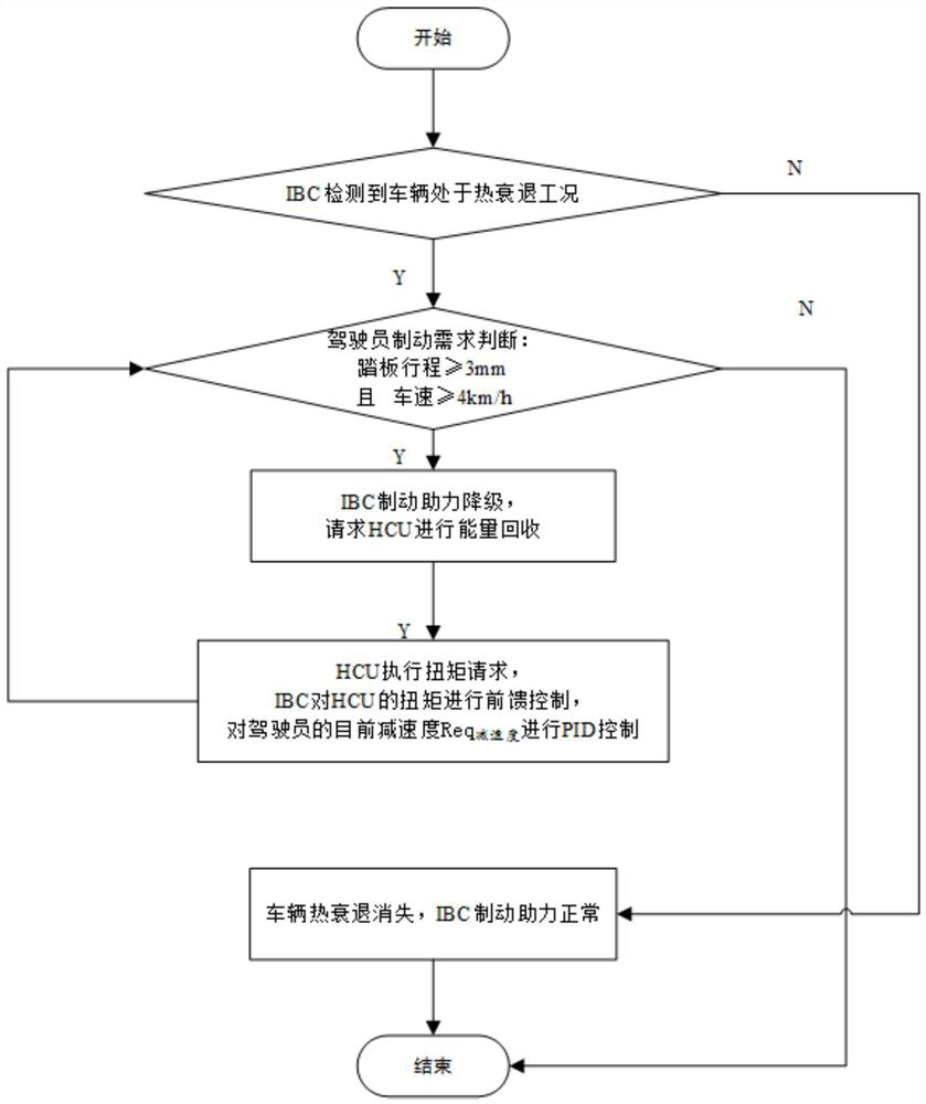
[0028] refer to figure 1 , a method for controlling deceleration of a brake disc under a heat decay condition, comprising the following steps:

[0029] Step 1. IBC detects whether the vehicle is in the condition of heat decay; if IBC recognizes that the vehicle is in the condition of brake disc heat decay, perform step 2; if the problem of vehicle heat decay disappears, the IBC brake assist is normal; the details are as follows:

[0030] IBC passes the estimated brake disc temperature and reaches the driver's dem...


PUM


Abstract

The invention belongs to the technical field of automobiles, and particularly relates to a deceleration control method under the heat fading working condition of a brake disc. The method aims at guaranteeing the braking safety of a driver to the maximum extent, under the working conditions of long downhill and heavy disc heat fading, the IBC aims at relieving the heat fading of the brake disc andreducing the hydraulic braking assistance after recognizing the working conditions, and the difference between the actual deceleration of a vehicle and the target acceleration of the driver comes fromtwo aspects at the moment, wherein one aspect is the difference caused by heat fading of the brake disc, and the other aspect is the difference caused by reducing the hydraulic brake boosting value by the IBC; and then the IBC converts the deceleration difference into a recovery torque to request the HCU to perform brake energy recovery, finally, the deceleration target of a driver is achieved, meanwhile, the heat fade condition of the brake disc can be effectively relieved, and the safety problem of insufficient brake force in the prior art is solved.

Description

technical field [0001] The invention belongs to the technical field of automobiles, and in particular relates to a deceleration control method under the condition of brake disc thermal decline. Background technique [0002] At present, in order to seek high braking performance for hybrid vehicles or electric vehicles, many OEMs are equipped with integrated brake control assembly (Integrated brake control assembly, hereinafter collectively referred to as IBC). IBC products integrate the electronic stability control system of traditional vehicles. (Electronic Stability Control, ESC), vacuum booster and vacuum pump can provide all the functions of the original ESC system, and can also provide the brake boosting function responsible for the vacuum booster and vacuum pump. Different from the traditional vacuum booster, the IBC What is provided is a decoupled brake booster function, that is, how deep the driver steps on the brake pedal, and the pressure chamber motor of IBC can pr...

Claims


Application Information

Patent Timeline
Patent Type & Authority Applications(China)
IPC IPC(8): B60T17/22B60T13/12
CPCB60T17/22B60T13/12
Inventor 邸丽伟徐华林官浩彭凯刘冬雨侯宗翰
Owner CHINA FIRST AUTOMOBILE
Why Eureka
Try Eureka