
Calibration device for measuring intensity distribution characteristics of road traffic signal lights

A technology of road traffic and distribution characteristics, applied in measurement devices, devices with multiple detectors, optical radiation measurement, etc., can solve the problems of stability error, measurement error, difficult to realize coaxial, etc., to solve the error of light intensity measurement Effect

Active Publication Date: 2022-05-20
JIANGSU INST OF METROLOGY
View PDF0 Cites 0 Cited by
  • Summary
  • Abstract
  • Description
  • Claims
  • Application Information

AI Technical Summary

Problems solved by technology

Using the measurement method of signal lamp rotation, there is a problem that its rotation axis is difficult to determine; secondly, the rotation axis of the lamp and the rotation axis of the turntable can be accurately measured
However, the two rotating shafts are not visible in space, so coaxiality is difficult to achieve, and large measurement errors will be introduced
[0008] (3) The luminescence of lamps and lanterns is not absolutely stable. The error caused by the stability is not only related to the type of lamp, but also the individual lamps and lanterns of the same manufacturer, model and batch have differences in luminescence stability.
Therefore, the luminous stability of the signal light will introduce a certain measurement error
[0009] (4) When incandescent lamps and low-voltage halogen lamps rotate non-horizontally, their filaments will be slightly deformed under gravity, which will also cause changes in light intensity values, resulting in the introduction of certain measurement errors

Method used


Image

  • Calibration device for measuring intensity distribution characteristics of road traffic signal lights
  • Calibration device for measuring intensity distribution characteristics of road traffic signal lights

Examples


Embodiment Construction

[0031] Below in conjunction with specific embodiment, further illustrate the present invention, should be understood that these embodiments are only used to illustrate the present invention and are not intended to limit the scope of the present invention, after having read the present invention, those skilled in the art will understand various equivalent forms of the present invention All modifications fall within the scope defined by the appended claims of the present application.

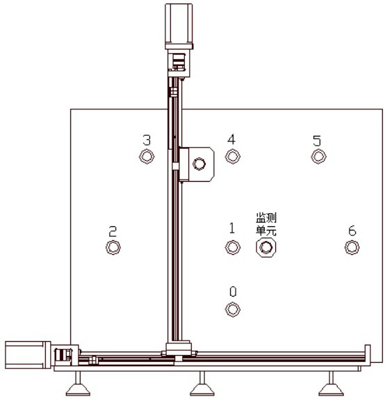
[0032] A calibration device for measuring the intensity distribution characteristics of road traffic signal lights, including an initial position positioning unit, a light source receiving unit, a light intensity distribution control unit, and a calibration unit.

[0033] In the traditional process of measuring the intensity distribution characteristics of road traffic signal light, (1) the rotation of the signal light in the non-horizontal direction will change the lighting posture of the light, a...


PUM


Abstract

The invention discloses a calibration device for measuring the intensity distribution characteristics of road traffic signal light, which includes an initial position positioning unit, a light source receiving unit, a light intensity distribution control unit, and a monitoring unit; the initial position positioning unit is turned on to complete the light intensity The distribution control unit determines and collects the measurement zero point on the light source receiving unit; starts the light intensity distribution control unit, moves the light intensity distribution control unit to the position of the point to be measured on the light source receiving unit, and collects the corresponding light intensity of the signal lamp at the point to be detected Data; in the process of collecting light intensity data, the monitoring unit collects the stability data of the signal light, and corrects the light intensity distribution data. The signal lamp of the present invention does not move, and the detector operates, which eliminates the measurement error caused by the change of the ignition posture of the signal lamp when it is rotated, the spatial misalignment of the rotation axis, the deformation of the filament, the instability of the light source during the measurement process, and the angle error caused by the turntable where the light source is placed. .

Description

technical field [0001] The invention relates to a calibration device for measuring the intensity distribution characteristics of road traffic signal lights, and belongs to the technical field of signal light intensity distribution measurement. Background technique [0002] Traffic lights, as the baton of urban traffic, play an increasingly important role in maintaining traffic order and ensuring traffic safety. Traffic signal lights: According to the purpose, traffic signal lights can be divided into three types: motor vehicle, non-motor vehicle and pedestrian crossing signal lights. Motor vehicle and non-motor vehicle signal lights usually have three colors: red, green, and yellow; pedestrian crossing signal lights usually have two colors: red and green. [0003] GB 14887-2011 "Road Traffic Signal Lights" stipulates the luminous intensity of traffic signal lights: the measurement distance of luminous intensity is 10m. For non-motor vehicle signal lights with LED outline p...

Claims


Application Information

Patent Timeline
Patent Type & Authority Patents(China)
IPC IPC(8): G01J1/42
CPCG01J1/4228G01J2001/4247
Inventor 张帆刘辉徐晓昂单睿康马涛刘皓
Owner JIANGSU INST OF METROLOGY
Learn More