Full-rail type railhead abrasion measuring device

A measuring device and rail head technology, which is applied in the field of guide rail measurement, can solve problems such as single measurement function, high requirements, and cost reduction, and achieve the effect of flexible adjustment and simple structure

Pending Publication Date: 2020-12-29
卜少明
View PDF0 Cites 2 Cited by
  • Summary
  • Abstract
  • Description
  • Claims
  • Application Information

AI Technical Summary

Problems solved by technology

[0003] The rail wear meter in the prior art has a relatively single measurement function. A rail wear meter can only measure the top wear of the rail head and the wear of the side working surface of the rail head of a certain type of rail, and it must be used before using the rail wear meter. The inspection tool must be calibrated to zero first, and then the measured rail can be compared and measured to obtain the wear of the top of the rail head and the wear of the working surface on the side of the rail head.
[0004] The existing rail wear meter can only measure a specific rail, and has high requirements for the standard gauge for zero and the working environment; at the same time, each work section of the railway transportation department must be equipped with it because it needs to measure rails of different rails Different types of rail wear gauges and different standard inspection tools are not conducive to the cost reduction and tool management of the rail transportation department, and cannot meet the rapid measurement needs of different rails in the rapid development of modern rail transportation

Method used


Image

  • Full-rail type railhead abrasion measuring device
  • Full-rail type railhead abrasion measuring device
  • Full-rail type railhead abrasion measuring device

Examples


Embodiment Construction

[0022] The technical solutions of the present invention will be further described below in conjunction with the embodiments shown in the accompanying drawings.

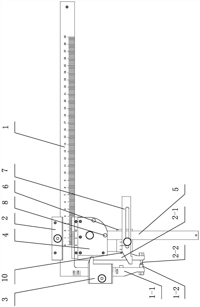
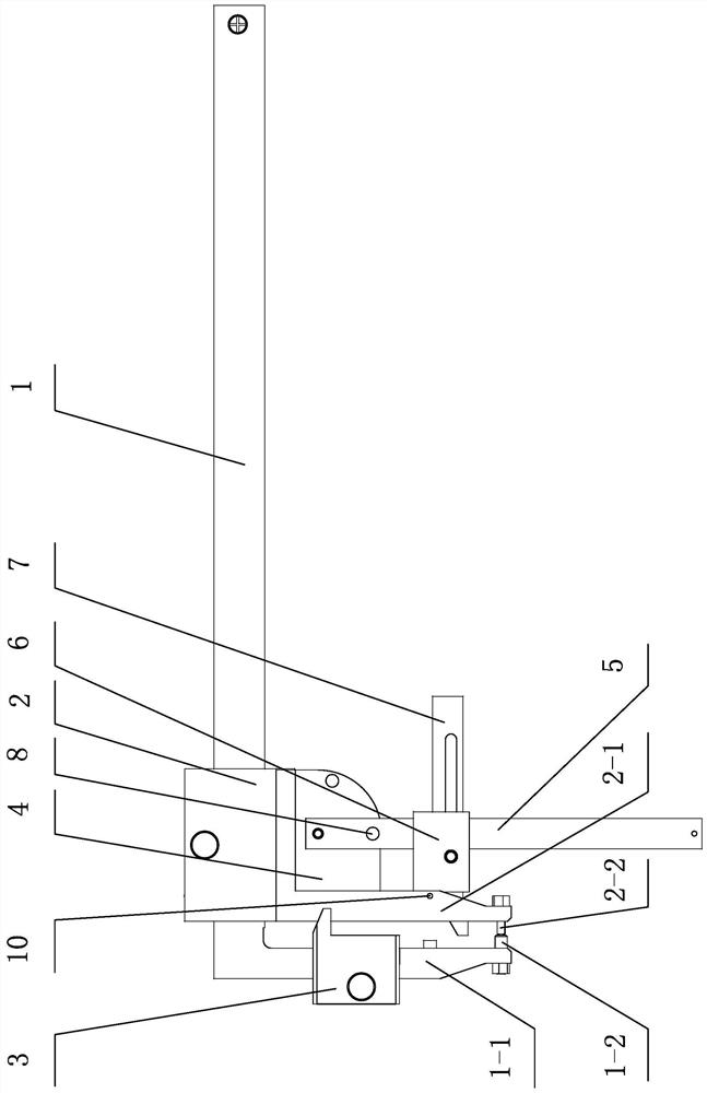
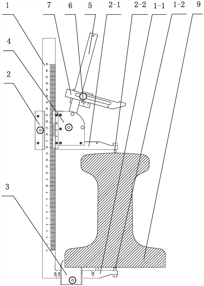
[0023] The full-rail type rail head wear measuring device of the present invention comprises a caliper frame 1 and a caliper frame 2, the caliper frame 2 is installed on the caliper body 1 and can be manually operated to slide forward and backward on the caliper body 1, so The bottom of the ruler body measuring claw 1-1 of the caliper ruler body 1 is provided with a backward ruler body measuring head 1-2, and a plurality of scale lines are engraved on the ruler body measuring claw 1-1 from top to bottom, Each scale line is the measurement position of the type UIC60 (the largest heavy rail), UIC50... UIC38 (the smallest light rail) or other types of rail 9 specified by the International Union of Railways, and the size of the UIC60, UIC50... UIC38 type rail 9 Decrementally, the bottom of the ruler frame measuring jaw 2-...


PUM


Abstract

The invention discloses a full-rail type railhead abrasion measuring device. The full-rail type railhead abrasion measuring device comprises a caliper body and a caliper frame sliding on the caliper body front and back, wherein a measuring block sliding up and down to adjust the measuring position is arranged on a caliper body measuring claw; a right-angle positioning bayonet is formed in the rearside of the measuring block; a supporting plate is arranged on the rear side of a caliper frame measuring claw; one end of a swing rod is hinged to the supporting plate; a sliding block is arranged on a rod body of the swing rod; a measuring rod is arranged on the sliding block in the direction perpendicular to the rod body in a sliding mode; a right-angle measuring head composed of a bottom measuring face and a top measuring face is arranged at the front end of the measuring rod; a stop pin for limiting the swing rod in the vertical position is arranged on the supporting plate; the top measuring face of the measuring rod is aligned with the caliper frame measuring head; and a reading ruler II on the measuring rod and a dividing ruler II on the sliding block are aligned to zero. The full-rail type railhead abrasion measuring device can measure abrasion of the tops and the side faces of different rail type guide rail railheads, the types and the number of detection tools needing to bearranged are reduced, the operation process is simplified, and the cost of the detection tools is reduced.

Description

technical field [0001] The invention relates to a guide rail measurement technology in rail transportation, in particular to a full-rail type rail head wear measurement device. Background technique [0002] In the process of processing and testing the rails used in rail transportation, it is often necessary to measure the wear of the rail head on various rails of different sizes and shapes. [0003] The rail wear meter in the prior art has a relatively single measurement function. A rail wear meter can only measure the top wear of the rail head and the wear of the side working surface of the rail head of a certain type of rail, and it must be used before using the rail wear meter. The inspection tool must be calibrated to zero first, and then the measured rail can be compared and measured to obtain the wear of the top of the rail head and the wear of the working surface on the side of the rail head. [0004] The existing rail wear meter can only measure a specific rail, and...

Claims


Application Information

Patent Timeline
Patent Type & Authority Applications(China)
IPC IPC(8): G01B5/00G01B5/06
CPCG01B5/0004G01B5/061
Inventor 卜少明
Owner 卜少明
Why Eureka
Try Eureka