Window guardrail with security function

A guardrail and functional technology, which is applied in the field of window guardrails with security functions, can solve the problems of security performance degradation of safety window guardrails, accelerated oxidation and rust of iron metals, etc.

Inactive Publication Date: 2020-12-29
成都儒气合商贸有限公司
View PDF0 Cites 0 Cited by
  • Summary
  • Abstract
  • Description
  • Claims
  • Application Information

AI Technical Summary

Problems solved by technology

[0003] If the safety window guardrail is installed on a window that is lower than the ground on the first floor, and vines such as ivy will be planted around the walls of some buildings for landscaping, so that the ivy under the window will easily become entangled in the safety protection when it grows up. As a result, the root of the creeper will scratch the aging paint on the iron metal pipe that has been used for a long time when it extends out, which will cause the iron metal to be prone to accelerated oxidation and rust, thus deteriorating the security performance of the safety window guardrail. decline

Method used


Image

  • Window guardrail with security function
  • Window guardrail with security function
  • Window guardrail with security function

Examples


Embodiment 1

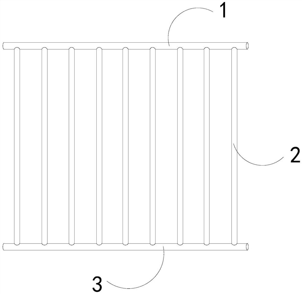
[0026] For example figure 1 -example Figure 5 Shown:

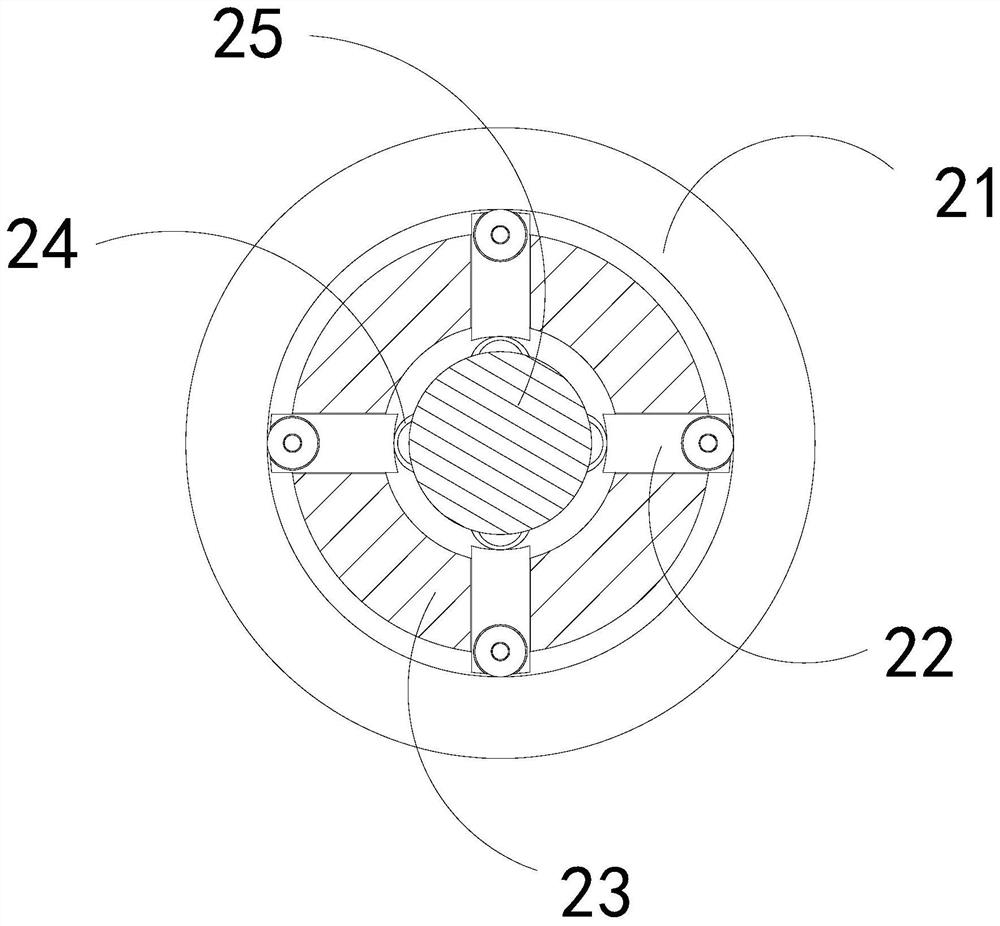
[0027] The invention provides a window guardrail with security function, its structure includes an upper connecting rod 1, a railing 2, and a lower connecting rod 3, the upper connecting rod 1 is fixed at the upper end of the railing 2, the railing 2 and the lower connecting rod 3 are connected; the railing 2 includes an outer tube 21, a connecting strip 22, an inner ring 23, an elastic piece 24, and a solid block 25, the outer tube 21 is engaged with the outer part of the inner ring 23, and the connecting bar 22 The inner ring 23 is loosely matched with the inner ring 23 and the middle solid block 25 is an integrated structure, and the elastic sheet 24 is embedded and fixed between the connecting strip 22 and the middle solid block 25 .

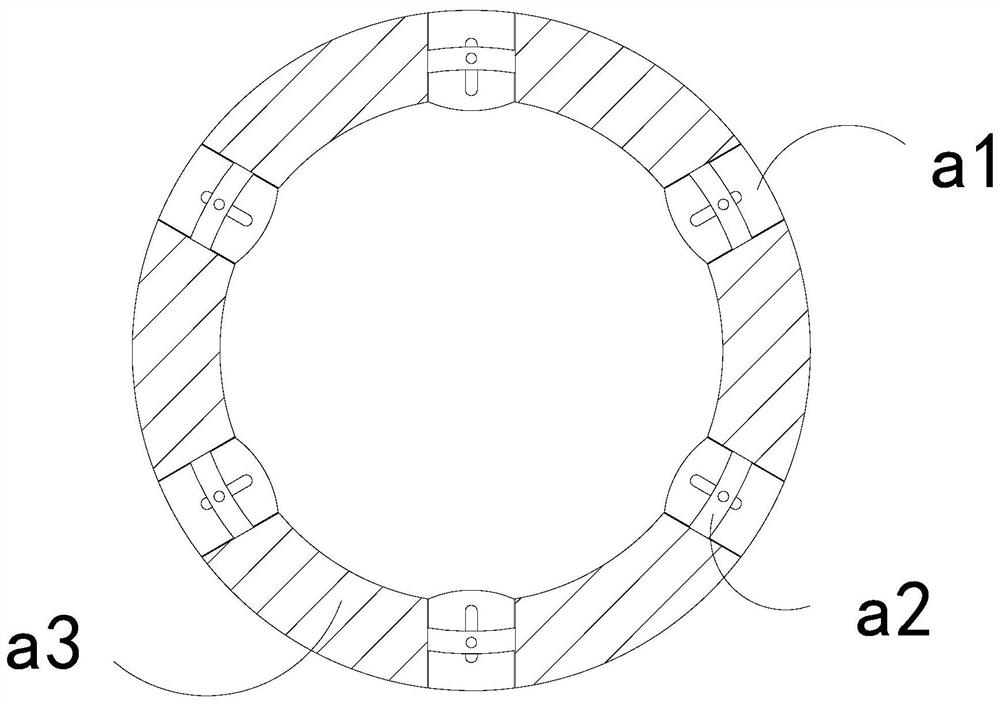
[0028] Wherein, the outer tube 21 includes a pushing block a1, a fixing plate a2, and a receiving ring a3, the pushing block a1 is movably engaged with the fixing plate a2, and the fi...

Embodiment 2

[0034] For example Figure 6 -example Figure 8 Shown:

[0035] Wherein, the top board a11 includes an upper board c1, a bottom board c2, a connecting rod c3, and an overhanging block c4. Together, the overhanging block c4 is embedded and fixed at the upper end of the connecting rod c3. There are three overhanging blocks c4, which are evenly distributed in an arc on the upper plate c1. The inertial force can make the connecting rod c3 push the overhanging block c4 to protrude outward.

[0036] Wherein, the outstretching block c4 includes a resilient piece c41, a bottoming plate c42, and an outreaching plate c43. The resilient piece c41 is installed between two outreaching plates c43. Combined, the said outboard c43 is provided with two, and evenly distributed symmetrically on the upper surface of the base plate c42, through the springback piece c41 can push the a43 that has lost the inner wall of the object to slide to the outside, so that the outboard C43 can push away th...


PUM


Abstract

The invention discloses a window guardrail with a security function. The window guardrail structurally comprises an upper connecting rod, handrails and a lower connecting rod, the upper connecting rodis fixed to the upper ends of the handrails, and the handrails are connected with the lower connecting rod. Through outer pipes on the handrails, when parthenocissus tricuspidata is wound around theouter surfaces of the outer pipes, the whole parthenocissus tricuspidata generates downward gravity pulling on the outer pipes, thus the outer pipes can rotate along a connecting strip, so that parthenocissus tricuspidata vines wound on the outer surfaces of the outer pipes can be reversely rotated out, and the situation that the roots of parthenocissus tricuspidata penetrate into the space between an outer push block and the inner wall of a bearing ring can be avoided; through springback pieces, outer unfolding plates which lose extrusion of the inner wall of an upper placing plate can be pushed towards the two sides to slide and unfold towards the two sides, so that pulling blocks can be blocked by the parthenocissus tricuspidata to swing upwards, and thus the pulling blocks can pull apart the roots of parthenocissus tricuspidata vines wound on the outer surfaces of the handrails along with the outer unfolding plates in the unfolding process.

Description

technical field [0001] The invention relates to the security field, in particular to a window guardrail with a security function. Background technique [0002] The security window guardrail is mainly used for the safety protection of the window area. It is usually installed on the outside of the window to improve the safety performance of the window, and the security window guardrail is mostly made of stainless steel or painted iron metal pipes. Common equipment in life, based on the above description, the inventor found that the existing window guardrail with security function mainly has the following deficiencies, for example: [0003] If the safety window guardrail is installed on a window that is lower than the ground on the first floor, and vines such as ivy will be planted around the walls of some buildings for landscaping, so that the ivy under the window will easily become entangled in the safety protection when it grows up. As a result, the root of the creeper will...

Claims


Application Information

Patent Timeline
Patent Type & Authority Applications(China)
IPC IPC(8): E06B9/01E06B7/28
CPCE06B7/28E06B9/01
Inventor 李志儒
Owner 成都儒气合商贸有限公司
Why Eureka
Try Eureka