


Quick Research
Generate reliable direction feasibility study reports for your R&D in just a few steps.

Technical Q&A
Discover and master advanced knowledge NOW. Basics, ideas, possibilities, all at once.

Find Solutions
As an expert in R&D theories, this can generate solutions to your technical problems instantly.

Evaluate Feasibility
Analyze your overall solution with one click, know your potential R&D risks in advance.

Monitor Landscape
Get weekly tech updates, stay abreast of the latest tech innovations and key insights.
Main keel structure and keel frame
A main keel and keel technology, applied to building components, building structures, buildings, etc., can solve the problems of insufficient structural stability, insufficient assembly speed, inconvenient operation, etc., to achieve good assembly and support, reduce The effect of the use of connectors and the improvement of stability
- Summary
- Abstract
- Description
- Claims
- Application Information
AI Technical Summary
Problems solved by technology
Method used
Image

Examples
Embodiment 1
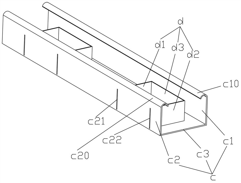
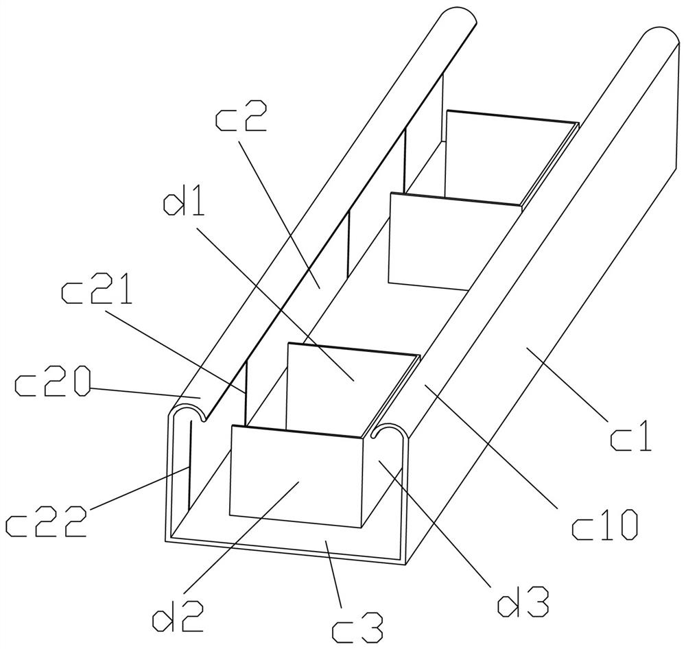
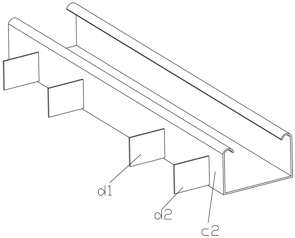
[0039] Example 1, such as Figure 1-4 As shown, a main keel structure includes a main keel c, and the main keel c includes a front main keel plate c1, a rear main keel plate c2, and the bottom and rear of the front main keel plate c1, which are arranged front and back and are upright The bottom of the main keel c2 is integrally connected with the flat bottom main keel c3, so the structure of the main keel c is a U-shaped structure with an upward opening and a U-shaped groove structure. Specific implementation The front and back direction in the embodiment refers to the direction from the center of the suspended ceiling to the edge of the outer wall, because there will be one keel of this structure near each side wall, and then each main keel c is surrounded to form a frame-shaped surrounding structure , the bottom of the bottom main joist board c3 is used to decorate wall panels such as gypsum boards, and then the rear main joist board c2 of each main joist will connect the au...
Embodiment 2
[0047] Example 2, such as Figure 5-6 As shown, a keel frame, which can also be referred to as a keel assembly, includes the main keel structure in Embodiment 1, and also includes an auxiliary keel g and a top keel h, and the top keel h and the main keel The keel c hangs up and down, and the auxiliary keel g is plugged into the rear plug-in suspension buckle d.
[0048] Specifically, the auxiliary keel g has two or more installations with the main keel c. The auxiliary keel g extends backwards and maintains a vertical state with the main keel as far as possible. The structure of the auxiliary keel g is also preferably U-shaped, but the opening faces The upper part includes the left sub-panel g1, the right sub-panel g2, and the bottom sub-panel g3 integrally connected between the bottom of the left sub-panel g1 and the bottom of the right sub-panel g2. The top of the left sub-panel g1 is integrally connected with an inwardly rolled left Secondary curling g10, the top of the ri...
Embodiment 3
[0050] Example 3, such as Figure 7-11 and of Example 2 Figure 6 As shown, a keel connector includes a middle up and down adjustment support part and a left connecting plate e1 and a right connecting plate e2 respectively connected to the left and right sides of the middle up and down adjusting support part extending downward and used to connect to the keel, The left connecting plate e1 and the right connecting plate e2 are used to directly install and connect with the keel. The orientation here refers to the state where the keel connecting piece is placed upright. The left connecting plate e1 and the right connecting plate e2 are used to follow the bottom The keel is connected. Of course, this keel connector can be used upside down to connect with the upper keel. Use the inverted keel connector and another keel connector that is placed up and down to connect. There are two upper and lower keels, and the details will be discussed later. In addition, regarding the middle up ...
PUM
 Abstract
Description
Claims
Application Information
 - R&D Engineer
- R&D Manager
- IP Professional
- Industry Leading Data Capabilities
- Powerful AI technology
- Patent DNA Extraction
Browse by: Latest US Patents, China's latest patents, Technical Efficacy Thesaurus, Application Domain, Technology Topic, Popular Technical Reports.
© 2024 PatSnap. All rights reserved.Legal|Privacy policy|Modern Slavery Act Transparency Statement|Sitemap|About US| Contact US: help@patsnap.com