Grooving device for reinforcing groove of chopping board

A technology for fastening devices and chopping boards, which is applied to slotting machines, clamping devices, and mortising machines, etc., can solve the problems of low work efficiency, cumbersome operation, laborious work, etc., and achieve the effect of high work efficiency and convenient operation

Active Publication Date: 2020-12-29
临沂临港国有资产运营集团有限公司
View PDF7 Cites 7 Cited by
  • Summary
  • Abstract
  • Description
  • Claims
  • Application Information

AI Technical Summary

Problems solved by technology

[0005] In order to overcome the need to draw the slotting position on the outside of the chopping board in the circumferential direction, and then use the tool to slot, the operation is cumbersome, the work efficiency is low, and the tool needs to be moved continuously for slotting, which is laborious. The technical problems to be solved are: Provided is a cutting board reinforcement groove slotting device that can replace manual slotting in the outer circumferential direction of the cutting board, is easy to operate, has high work efficiency, and saves labor

Method used


Image

  • Grooving device for reinforcing groove of chopping board
  • Grooving device for reinforcing groove of chopping board
  • Grooving device for reinforcing groove of chopping board

Examples


Embodiment 1

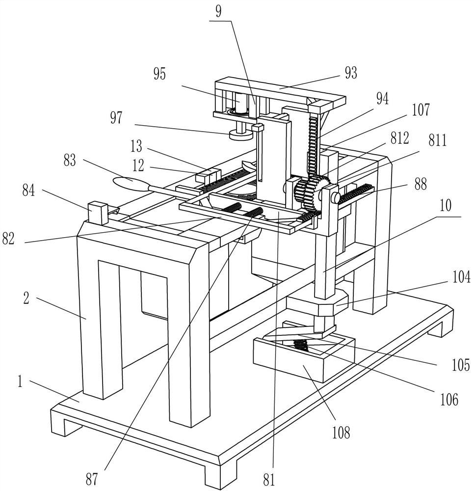
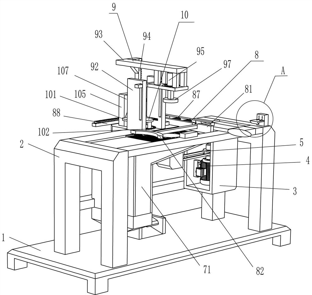
[0026] A cutting board reinforcing groove slotting device, such as Figure 1-Figure 6 As shown, it includes a base 1, a workbench 2, a bracket 3, a gear motor 4, a transmission assembly 5, a first rotating shaft 6, a contact pad 7, a hopper 71, a pushing device 8, a fastening device 9 and a slotting mechanism 10 , the top of the base 1 is fixedly connected with the workbench 2, and the middle of the upper front side of the workbench 2 is connected with the first rotating shaft 6 in a rotational manner, and the top of the first rotating shaft 6 is fixedly connected with the contact pad 7, and the contact pad 7 is embedded in the workbench 2, a bracket 3 is fixedly connected to the right front part of the inner top of the workbench 2, and a geared motor 4 is installed in the middle of the inner bottom of the bracket 3, and a transmission assembly 5 is connected between the output shaft of the geared motor 4 and the lower circumferential direction of the first rotating shaft 6. C...

Embodiment 2

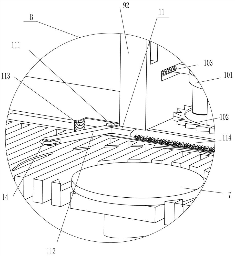
[0035] On the basis of Example 1, such as image 3 with Figure 5 As shown, it also includes a dust removal device 11. The dust removal device 11 includes a third rotating shaft 111, a contact rod 112, a fifth spring 113 and a hair brush 114. The upper part of the workbench 2 is connected with a rotating type on the left side of the rear side. Three rotating shafts 111, the third rotating shaft 111 is affixed with a contact rod 112, the right end of the contact rod 112 is affixed with a brush 114, and a fifth spring 113 is connected between the outer left side of the contact rod 112 and the inside of the workbench 2.

[0036] When the push rod 82 drives the cutting board to move to the left and disengage from the contact pad 7, the cutting board contacts the contact rod 112, and the cutting board drives the front part of the contact rod 112 to swing to the left, the fifth spring 113 compresses, and the front part of the contact rod 112 swings to the left so that The right par...

Embodiment 3

[0038] On the basis of embodiment 1 and embodiment 2, such as figure 2 , image 3 with Figure 5 As shown, sandpaper 12 and installation block 13 are also included, and installation block 13 is affixed to the middle part of the front side of the outer top of workbench 2, and sandpaper 12 is affixed to the middle part of the rear side of installation block 13.

[0039] It also includes a guide wheel 14, and the front end of the contact rod 112 is rotatably equipped with the guide wheel 14.

[0040] After the cutting board was compressed, the cutting board was also in contact with the sandpaper 12, and then when the cutting board was rotated and slotted by the saw disc 102, the sandpaper 12 removed the burrs that occurred after the slotting. In this way, the outer circumferential groove of the cutting board can be made smoother.

[0041] When the chopping block moved to the left, the chopping block drove the contact rod 112 front portion to swing to the left by the guide whe...


PUM


Abstract

The invention relates to a grooving device, in particular to a grooving device for a reinforcing groove of a chopping board. The technical problem is to design the grooving device for the reinforcinggroove of the chopping board which can replace manpower in conducting grooving in the circumferential direction of the outer side of the chopping board, and is convenient to operate, high in working efficiency and capable of saving labor. The grooving device for the reinforcing groove of the chopping board comprises a base and a support; a workbench is fixedly connected with one side of the base;and the support is fixedly connected to the side, facing the base, of the workbench. A material pushing rod is pulled to move rightwards to a proper position, the chopping board is placed right over acontact pad to make contact with the contact pad, the material pushing rod is continuously pulled to move rightwards so that a fastening block can tightly press the chopping board, a deceleration motor is started, the contact pad drives the chopping board to rotate, and a saw disc makes contact with the outer side of the chopping board in the circumferential direction so that the cutting board can be grooved. People do not need to manually groove the outer side of the chopping board in the circumferential direction, operation is convenient, and working efficiency is high.

Description

technical field [0001] The invention relates to a slotting device, in particular to a slotting device for reinforcing slots of an anvil board. Background technique [0002] The chopping board refers to the utensils that are placed underneath when hammering, cutting, chopping, or smashing things. It is generally used for cooking. Grooves are made on the circumference, and the iron ring is installed in the groove to fix the chopping board, making the chopping board more stable. [0003] At present, most of the cutting boards are manually grooved on the outside of the cutting board. First, people need to use a pen to draw the slotting position on the outside of the cutting board, and then use a knife and a hammer to make grooves on the outside of the cutting board. This operation It is rather cumbersome, resulting in low work efficiency, and due to the need to continuously move the cutter to slot the cutting block in the outer circumferential direction, it is more laborious. ...

Claims


Application Information

Patent Timeline
IPC IPC(8): B27B5/02B27B29/02B27B5/18B27B5/29B27F5/02B24B9/18B27C9/00B27G3/00
CPCB27B5/02B27B29/02B27B5/187B27B5/29B27F5/02B24B9/18B27C9/00B27G3/00Y02P70/10
Inventor 刘刚
Owner 临沂临港国有资产运营集团有限公司
Why Eureka
Try Eureka