


Quick Research
Generate reliable direction feasibility study reports for your R&D in just a few steps.

Technical Q&A
Discover and master advanced knowledge NOW. Basics, ideas, possibilities, all at once.

Find Solutions
As an expert in R&D theories, this can generate solutions to your technical problems instantly.

Evaluate Feasibility
Analyze your overall solution with one click, know your potential R&D risks in advance.

Monitor Landscape
Get weekly tech updates, stay abreast of the latest tech innovations and key insights.
Equipment centering method, system and device and electronic equipment
An equipment pair, equipment technology, applied in measuring devices, workpiece clamping devices, instruments, etc., can solve problems such as damage to key components, collisions, and difficulty in guaranteeing gearboxes, so as to improve accuracy and efficiency, save human resources and The effect of time resources
- Summary
- Abstract
- Description
- Claims
- Application Information
AI Technical Summary
Problems solved by technology
Method used
Image

Examples
Embodiment 1
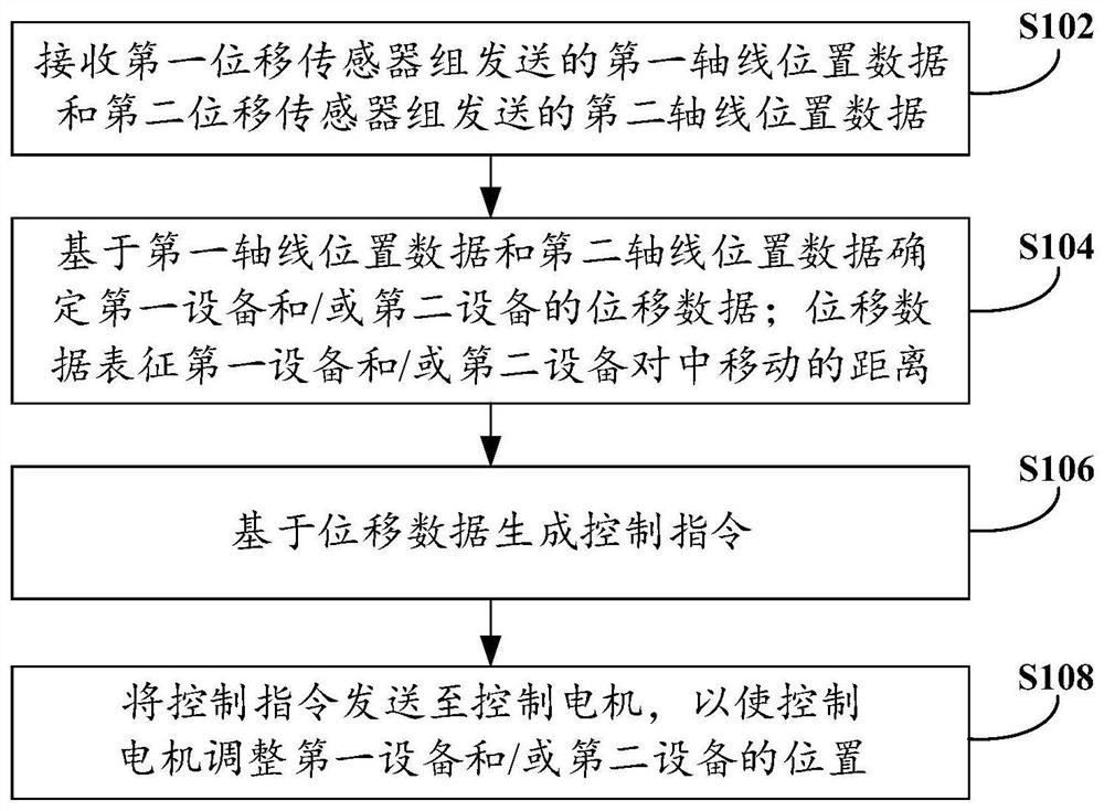
[0030] An embodiment of the present invention provides a device centering method, which is applied to a controller in a device centering system, and the device centering system further includes a first device, a second device, a first displacement sensor group and a second displacement sensor group sensor group, the first displacement sensor group and the second displacement sensor group are connected to the controller in communication, the shaft hole of the first device is provided with a first auxiliary shaft, and the shaft hole of the second device is A second auxiliary shaft is arranged in the hole, the first displacement sensor group is used to detect the first axis position data of the first auxiliary shaft, and the second displacement sensor group is used to detect the first axis position data of the second auxiliary shaft. Two-axis position data.
[0031]The first device and the second device may be two devices that need to be aligned. In this embodiment, the first dev...
Embodiment 2
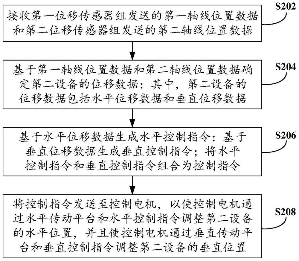
[0047] The embodiment of the present invention also provides another device centering method; this method is implemented on the basis of the methods in the above embodiments; this method focuses on the specific implementation of the device centering method in which the first device is fixed and the second device can be moved.
[0048] Such as figure 2 A flow chart of another device centering method is shown, the device centering method includes the following steps:
[0049] Step S202, receiving the first axis position data sent by the first displacement sensor group and the second axis position data sent by the second displacement sensor group.
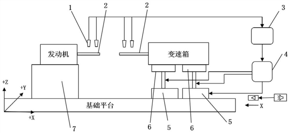
[0050] This embodiment mainly describes the situation where the first device is fixed and cannot be moved, but the second device can be moved, see image 3 A schematic diagram of an equipment centering system is shown, the engine is the first equipment, the gearbox is the second equipment, the first equipment and the second equipmen...
Embodiment 3
[0066] An embodiment of the present invention provides an equipment centering system, see Figure 4 A structural schematic diagram of an equipment centering system is shown, the centering system includes: a controller, a first device, a second device, a first auxiliary shaft, a second auxiliary shaft, a first displacement sensor group, and a second displacement sensor Group and control the motor; wherein, the first auxiliary shaft is arranged in the shaft hole of the first device, the second auxiliary shaft is arranged in the shaft hole of the second device, the first displacement sensor group and the second displacement sensor group are connected with the controller communication connection;
[0067] The controller is used for the above equipment centering method; the first displacement sensor group is used to detect the first axis position data of the first auxiliary shaft; the second displacement sensor group is used to detect the second axis position data of the second aux...
PUM
 Abstract
Description
Claims
Application Information
 - R&D Engineer
- R&D Manager
- IP Professional
- Industry Leading Data Capabilities
- Powerful AI technology
- Patent DNA Extraction
Browse by: Latest US Patents, China's latest patents, Technical Efficacy Thesaurus, Application Domain, Technology Topic, Popular Technical Reports.
© 2024 PatSnap. All rights reserved.Legal|Privacy policy|Modern Slavery Act Transparency Statement|Sitemap|About US| Contact US: help@patsnap.com