
Distributed all-coherent sparse linear array radar system optimization array method

A coherent radar, linear array technology, applied in the field of communication, can solve the problem of antenna pattern performance deterioration, etc.

Pending Publication Date: 2020-12-25
XIAN INSTITUE OF SPACE RADIO TECH
View PDF0 Cites 3 Cited by
  • Summary
  • Abstract
  • Description
  • Claims
  • Application Information

AI Technical Summary

Problems solved by technology

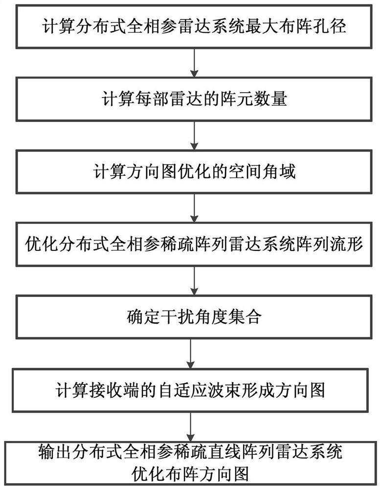
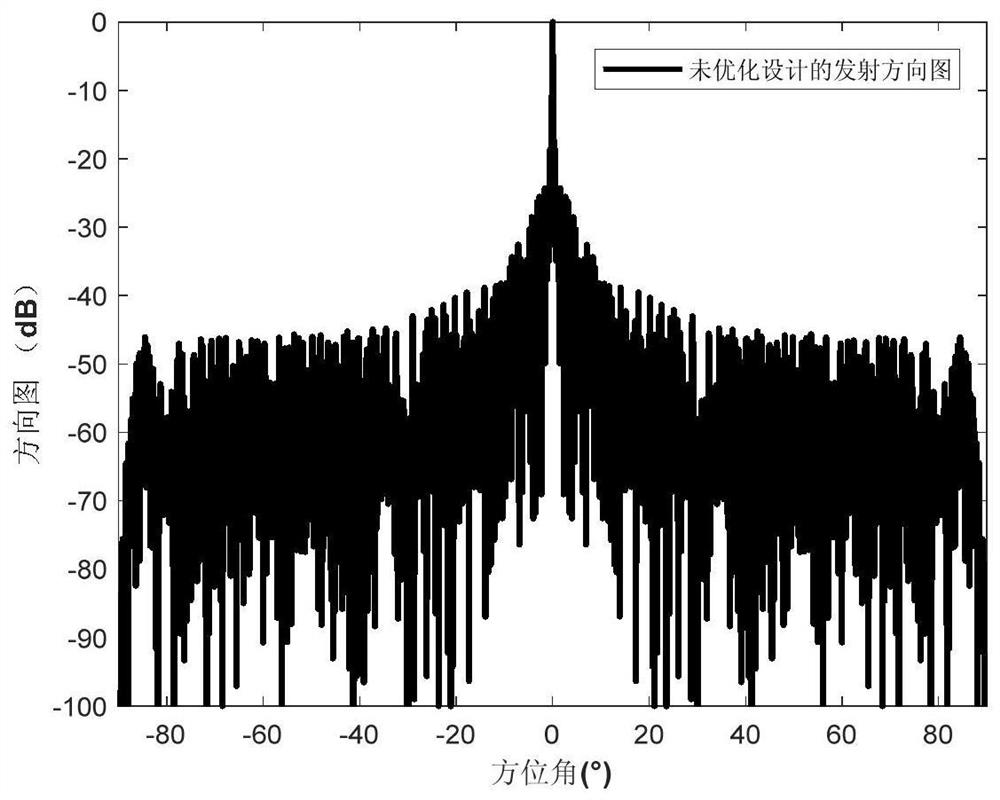
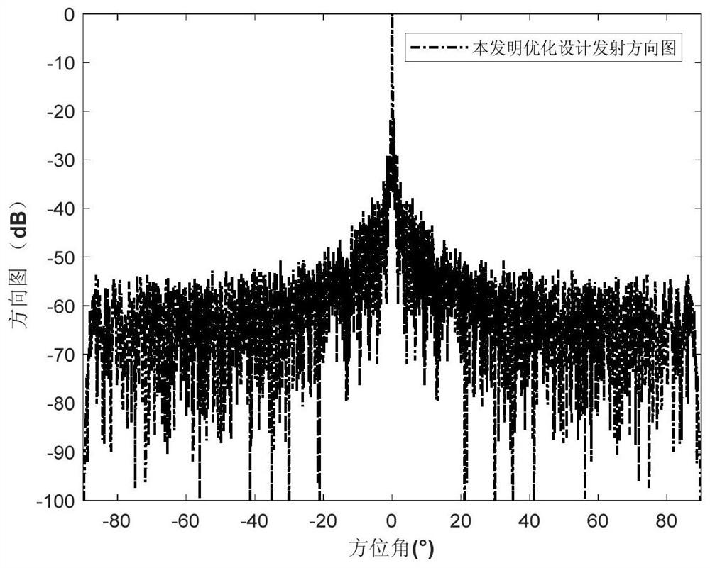
[0004] The technical problem solved by the present invention is: to overcome the deficiencies of the above-mentioned prior art, and to provide a distributed fully coherent sparse linear array radar system optimization array method, by using the degree of freedom of the array position to optimize the antenna pattern performance of the local space angle, At the same time, combined with airspace adaptive beamforming, a null trap is formed at the grating lobe interference position in the non-optimized area, and the performance of the transmitting and receiving antenna pattern is comprehensively improved, so as to solve the problem that the existing sparse array array optimization method cannot satisfy the distributed fully coherent sparse array radar array. The problem of the performance deterioration of the antenna pattern due to optimization requirements

Method used


Image

  • Distributed all-coherent sparse linear array radar system optimization array method
  • Distributed all-coherent sparse linear array radar system optimization array method
  • Distributed all-coherent sparse linear array radar system optimization array method

Examples


Embodiment Construction

[0058] The present invention will be further elaborated below in conjunction with embodiment.

[0059] The application scenario of the present invention is: the present invention can be applied to the sparse array full coherent radar array method for distributed radar to achieve better moving target detection capability, the distributed fully coherent radar is a linear array, each The array element configuration of each radar unit is the same. This method optimizes the performance of the antenna pattern at local spatial angles by using the degree of freedom of the array position, and at the same time combines the spatial adaptive beamforming to form a null at the grating lobe interference position in the non-optimized area, and comprehensively improves the performance of the transmitting and receiving antenna pattern to solve the existing problems. The sparse array array optimization method cannot meet the optimization requirements of the distributed fully coherent sparse arra...


PUM


Abstract

The invention relates to a distributed all-coherent sparse linear array radar system optimization array method, and aims to solve the problem that the performance of an antenna pattern is deteriorateddue to the fact that an existing sparse array optimization method cannot meet the array optimization requirement of a distributed all-coherent sparse linear array radar. The method comprises the following steps of: on the basis of considering the design and signal processing requirements of a distributed all-coherent radar system, calculating the maximum array aperture, the number requirement ofunit radar array elements and the directional diagram optimization angle of the distributed all-coherent sparse linear array radar system; then, carrying out sparse array optimization for a specific optimization angle domain; and then, screening discrete interference angles for a non-optimization angle area, forming nulls at interference positions by utilizing adaptive beamforming to inhibit interference, and finally outputting an optimized array directional diagram of the distributed all-coherent sparse linear array radar system.

Description

technical field [0001] The invention belongs to the technical field of communication, and further relates to a distributed fully coherent sparse linear array radar system optimized array method in the distributed motion platform radar technical field. The invention can be used in the array design of the distributed sparse array full coherent radar system to realize better detection ability of moving targets. Background technique [0002] The fully coherent distributed array radar transmits coherence through the antenna so that the power gain of the target to be detected reaches the third power of the number of channels, which significantly improves the detection performance of the radar for moving targets with low signal-to-noise ratio. [0003] The distance between the unit radars of the distributed fully coherent distributed array radar can reach hundreds of meters (much larger than the wavelength), which is represented as a sparsely distributed array, and the antenna tran...

Claims


Application Information

Patent Timeline
Patent Type & Authority Applications(China)
IPC IPC(8): G01S13/88G01S7/42
CPCG01S13/88G01S7/42
Inventor 田敏李财品段崇棣
Owner XIAN INSTITUE OF SPACE RADIO TECH
Learn More