Automatic driving vehicle test system and AEBS and FCWS test method
A technology of automatic driving and testing system, which is applied in the direction of vehicle testing, machine/structural component testing, measuring devices, etc. It can solve the problem that the performance testing environment cannot be integrated, it is not suitable for the batch test application of automatic driving vehicles, and it is unfavorable for the AEBS of automatic driving vehicles , FCWS test and evaluation methods, etc.
- Summary
- Abstract
- Description
- Claims
- Application Information
AI Technical Summary
Problems solved by technology
Method used
Image
Examples
Embodiment 1
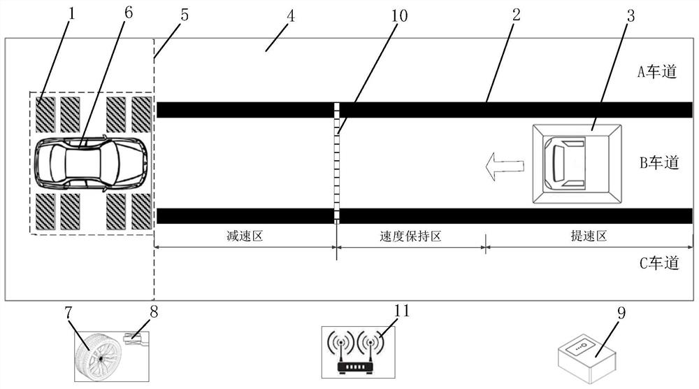
[0089] Such as figure 1 As shown, a self-driving vehicle test system includes a test site 4, a dynamometer 1, a vehicle under test 6, a communication device 11 and a console 9, and also includes a test background vehicle 3 and an induction magnetic strip 10. The test site 4 is marked with a lane line 2 and three lanes of A, B, and C are established, and the test site 4 is divided into a speed-up area, a speed-maintaining area, and a deceleration area perpendicular to the lane line 2; The induction magnetic strip 10 that is arranged on the B track between the speed maintenance areas is movable; the test background car 3 is located at one end of the test site 4, and is located in the A, B, and C lanes, and the test background car 3 is provided with an induction magnetic strip. The magnetic signal receiver of bar 10; the four-wheel output of the vehicle under test 6 is connected to the dynamometer 1, the vehicle under test 6 is located on the dynamometer 1, and is located at the ...
Embodiment 2
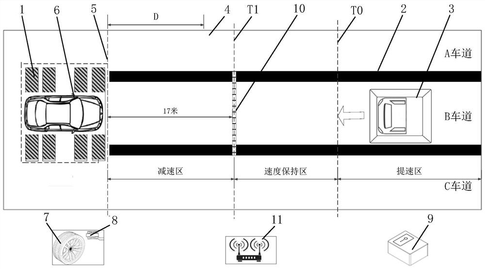
[0095] Such as figure 2 As shown, a schematic diagram of a self-driving vehicle AEBS longitudinal movement state performance test system, the test system includes a dynamometer 1, a test background car 3, a tire speed sensor 8 for measuring the speed of the vehicle tire 7 under test, a communication device 11, an induction The magnetic strip 10 is a magnetic signal receiver for receiving the signal of the induction magnetic strip 10, and the test background vehicle 3 is placed in the B lane. The test here simplifies the scene where the vehicle under test 6 drives towards the background vehicle at a certain speed under normal road conditions, and abstracts the vehicle under test 6 to stand still, but uses the dynamometer 1 to keep the vehicle under test 6 at the speed required for the test. In the mechanical state, the test background vehicle 3 moves towards the tested vehicle 6, thereby simulating the scene where the distance between the two vehicles is continuously shortened...
Embodiment 3
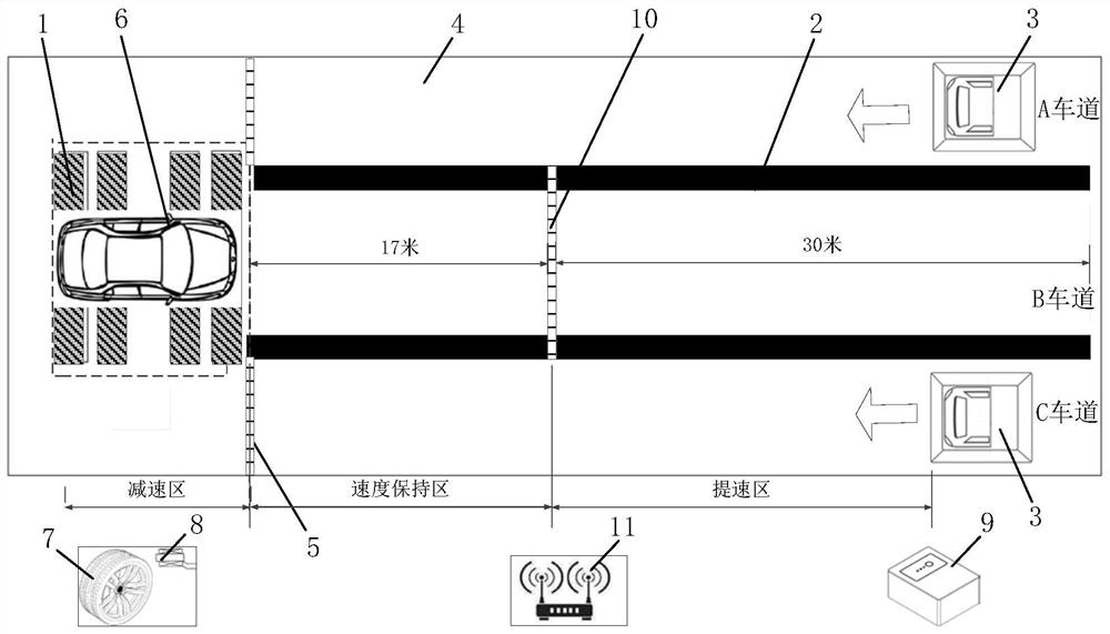
[0117] Such as image 3 As shown, a schematic diagram of an autonomous vehicle AEBS false response test system. Among them, the equipment involved includes: a dynamometer 1, a vehicle under test 6, two test background vehicles 3, a tire speed sensor 8 for measuring the rotation speed of the tire 7 of the vehicle under test, and a tire speed sensor 8 for controlling the vehicle under test 6 and the test background vehicle. 3 The console 9, the communication device 11, the induction magnetic strip 10 and the vehicle-mounted magnetic signal receiver etc. of the corresponding speed.
[0118] combine Figure 5 Understanding a false response test and evaluation method for AEBS of autonomous vehicles, including the following steps:
[0119] Step (S2100) Before the test starts, system initialization and self-testing of various equipment should be carried out. The two test background cars 3 are respectively located at the other end of the two adjacent lanes of the tested vehicle 6, a...
PUM
 Abstract
Description
Claims
Application Information
 - R&D
- Intellectual Property
- Life Sciences
- Materials
- Tech Scout
- Unparalleled Data Quality
- Higher Quality Content
- 60% Fewer Hallucinations
Browse by: Latest US Patents, China's latest patents, Technical Efficacy Thesaurus, Application Domain, Technology Topic, Popular Technical Reports.
© 2025 PatSnap. All rights reserved.Legal|Privacy policy|Modern Slavery Act Transparency Statement|Sitemap|About US| Contact US: help@patsnap.com


