Power monitoring equipment with safety protection function and application method thereof

A technology for power monitoring and safety protection, which is applied in the direction of cleaning methods, mechanical equipment, cleaning methods and utensils using tools. longevity, and the effect of preventing poor contact

Active Publication Date: 2020-12-25
GUANGXI POWER GRID ELECTRIC POWER RES INST
View PDF4 Cites 3 Cited by
  • Summary
  • Abstract
  • Description
  • Claims
  • Application Information

AI Technical Summary

Problems solved by technology

[0004] 1. The existing monitoring equipment needs to be fixed by screws during installation, which leads to the need to disassemble the screw before the device can be disassembled. During long-term use, due to the replacement and maintenance of parts, the position of the screw is repeatedly disassembled and installed, which is easy to cause slippage , finally making it impossible to fix the installation position, resulting in inconvenience:
[0005] 2. After the monitoring equipment is installed, it generally only has the monitoring effect and cannot perform heat dissipation work. As a result, it is difficult to dissipate the heat when the device is used for a long time. Working in a high temperature environment for a long time will reduce the service life of the device;
[0006] 3. During the long-term use of the monitoring equipment after installation, the position of the camera will be contaminated with dust, which will cause the camera picture to be blurred and affect the subsequent use effect, so a device is urgently needed to solve the above problems

Method used


Image

  • Power monitoring equipment with safety protection function and application method thereof
  • Power monitoring equipment with safety protection function and application method thereof
  • Power monitoring equipment with safety protection function and application method thereof

Examples


Embodiment Construction

[0035] The following will clearly and completely describe the technical solutions in the embodiments of the present invention with reference to the accompanying drawings in the embodiments of the present invention. Obviously, the described embodiments are only some, not all, embodiments of the present invention. Based on the embodiments of the present invention, all other embodiments obtained by persons of ordinary skill in the art without making creative efforts belong to the protection scope of the present invention.

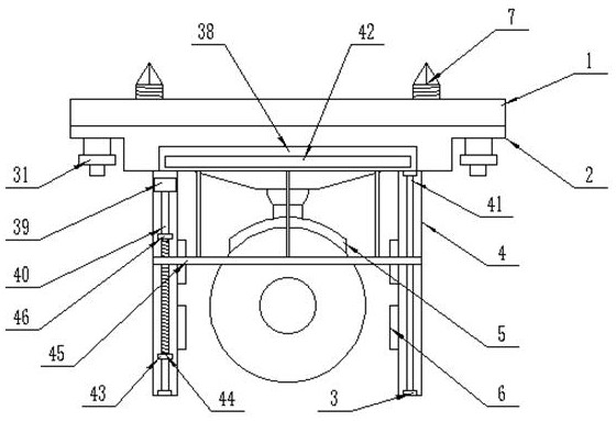
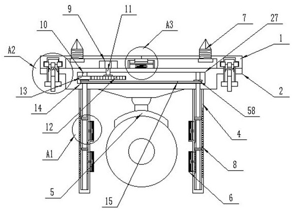
[0036] see Figure 1-8 , the present invention provides a technical solution: a power monitoring device with a safety protection function, including a mounting plate 1, a housing 2 and a vertical rod 4, the lower end of the housing 2 is fixedly installed with a camera body 5, so Both ends of the mounting plate 1 are vertically interspersed with fixing screws 7 through screw threads, and the mounting plate 1 can be fixedly installed at the destination position ...


PUM


Abstract

The invention discloses power monitoring equipment with a safety protection function. The power monitoring equipment with the safety protection function comprises an installation plate, a housing, anda vertical rod, wherein a camera main body is fixedly installed at the lower end of the housing; fixing screw rods are vertically inserted into two side ends in the installation plate in a penetrating manner; a first contact is fixedly mounted in the center of the upper wall in the installation plate; and the housing is arranged at the lower end of the installation plate. According to the power monitoring equipment with the safety protection function provided by the invention, a first motor drives a second rotating shaft to rotate, so that a first gear is driven to rotate, a second gear is driven to rotate, and first rotating shafts are driven to rotate; a third gear and a transmission chain drive a fourth gear to rotate, so that the first rotating shafts on two sides are in linkage and drive a first bevel gear to rotate; the first bevel gear drives a second bevel gear to rotate, so that a fourth rotating shaft rotates, and fan blades are driven to rotate; and heat dissipation work isconducted on the camera main body through generated wind power, so that the working temperature of the camera main body is reduced.

Description

technical field [0001] The invention relates to the field of monitoring equipment, in particular to a power monitoring equipment with a safety protection function and a method for using the same. Background technique [0002] The power monitoring system uses computers, communication equipment, and measurement and control units as basic tools to provide a basic platform for real-time data collection, switch status detection, and remote control of power transformation and distribution systems. It can form an arbitrarily complex monitoring system with detection and control equipment. It plays a central role in power transformation and distribution monitoring, which can help enterprises eliminate isolated islands, reduce operating costs, improve production efficiency, and speed up the abnormal response speed in the power transformation and distribution process. [0003] Some existing power monitoring systems also need to install a large number of cameras to monitor the working s...

Claims


Application Information

Patent Timeline
IPC IPC(8): F16M13/02F16M11/04B08B1/00G03B17/55H04N5/225
CPCF16M13/02F16M11/04G03B17/55H04N23/50B08B1/143
Inventor 乐开德
Owner GUANGXI POWER GRID ELECTRIC POWER RES INST
Why Eureka
Try Eureka