
Self-triggering magnetic control type anti-overspeed system for moving wheel rail

A self-triggering and moving wheel technology, applied in the direction of wheels, wheel-axle combinations, automatic brakes, etc., can solve the problems of lowering the anti-overspeed performance, increasing the economic cost of the device, and being prone to deformation, and achieves increased friction and better deceleration effect. Excellent, the effect of increasing friction

Active Publication Date: 2020-12-25
嘉禾县华伟铸造有限公司
View PDF6 Cites 0 Cited by
  • Summary
  • Abstract
  • Description
  • Claims
  • Application Information

AI Technical Summary

Problems solved by technology

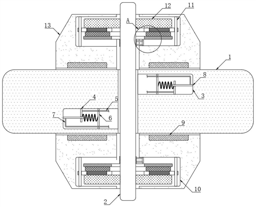
[0003] The existing safety devices are generally mechanical anti-overspeed hooks arranged on the moving wheels. These anti-overspeed hooks are prone to deformation due to repeated strong impacts after long-term use, resulting in the failure of the device. The overall anti-overspeed performance is reduced, and some electronic brake devices have appeared later. Compared with the anti-overspeed hook, these devices have improved anti-overspeed performance, but they need an external power supply when used, so the economic cost of the device is greatly increased. , in order to solve the above problems, it is necessary to design a self-triggering magnetic control anti-overspeed system for moving wheel rails

Method used


Image

  • Self-triggering magnetic control type anti-overspeed system for moving wheel rail
  • Self-triggering magnetic control type anti-overspeed system for moving wheel rail

Examples


Embodiment Construction

[0017] The following will clearly and completely describe the technical solutions in the embodiments of the present invention with reference to the accompanying drawings in the embodiments of the present invention. Obviously, the described embodiments are only some, not all, embodiments of the present invention.

[0018] In describing the present invention, it should be understood that the terms "upper", "lower", "front", "rear", "left", "right", "top", "bottom", "inner", " The orientation or positional relationship indicated by "outside", etc. is based on the orientation or positional relationship shown in the drawings, and is only for the convenience of describing the present invention and simplifying the description, rather than indicating or implying that the referred device or element must have a specific orientation, so as to Specific orientation configurations and operations, therefore, are not to be construed as limitations on the invention.

[0019] refer to Figure ...


PUM


Abstract

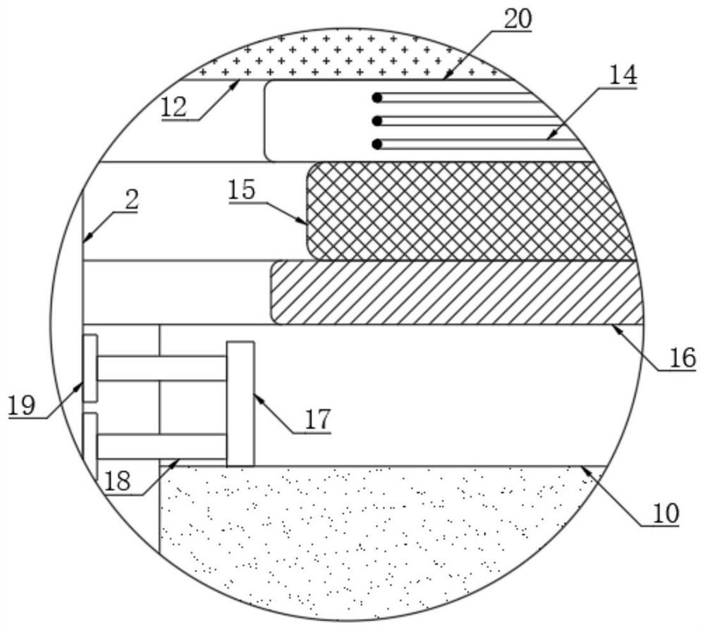
The invention discloses a self-triggering magnetic control type anti-overspeed system for a moving wheel rail. The system comprises a mounting block, a rotatable wheel shaft is arranged on the side wall of the mounting block in a penetrating mode, a rotating wheel is fixedly connected to the side wall of the wheel shaft, and two permanent magnet rings are fixedly embedded in the side wall of the mounting block. Two containing cavities are formed in the rotating wheel, fixing plates are fixedly connected to the inner walls of the two containing cavities correspondingly, first copper wires and second copper wires are fixedly inserted into the side walls of the two fixing plates correspondingly, resistor rods are fixedly connected to the inner walls of the two containing cavities correspondingly, and the side walls of the two resistor rods are slidably sleeved with conductive plates correspondingly. Two circular cavities are formed in the rotating wheel. When the running speed of a deviceis too high, a good deceleration effect can be achieved, the situation that the device deviates from a rail due to the too high running speed is prevented, the safety performance of the device is improved, an external power source is not needed, and the economic cost of the device is saved.

Description

technical field [0001] The invention relates to the related technical field of moving wheel-rail equipment, in particular to a self-triggering magnetically controlled overspeed prevention system for moving wheel-rail. Background technique [0002] In the environment of building construction and factory workshops, it is often necessary to transport some objects or goods, and some wheel-rail transportation tools are usually used in the transportation process, such as some roadway trolleys used to transport coal mines and steel products etc. During transportation, in order to prevent these transportation equipment from being too fast, some safety devices for deceleration are usually set. [0003] The existing safety devices are generally mechanical anti-overspeed hooks arranged on the moving wheels. These anti-overspeed hooks are prone to deformation due to repeated strong impacts after long-term use, resulting in the failure of the device. The overall anti-overspeed performan...

Claims


Application Information

Patent Timeline
Patent Type & Authority Applications(China)
IPC IPC(8): B60B37/10B60B17/00B61H11/04
CPCB60B37/10B60B17/0006B61H11/04
Inventor 何小凤
Owner 嘉禾县华伟铸造有限公司
Learn More