Full-automatic visual inspection device and inspection method for precision electronic stamping part
A visual inspection, precision electronic technology, applied in measuring devices, chemical instruments and methods, cleaning methods and utensils, etc., can solve the problems of missed inspection, misjudgment, unfavorable production control, poor inspection accuracy, etc., to achieve stability and reliability. High performance, easy production management and control, and the effect of reducing production costs
- Summary
- Abstract
- Description
- Claims
- Application Information
AI Technical Summary
Problems solved by technology
Method used
Image
Examples
Embodiment 1
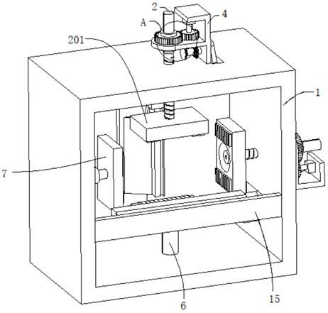
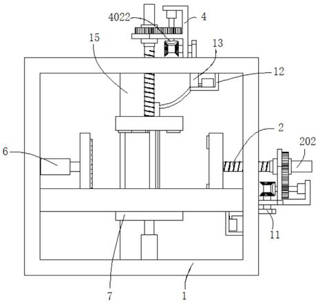
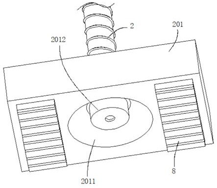
[0038] refer to Figure 1-5 , a fully automatic visual inspection equipment for precision electronic stamping parts, including a fixed frame 1, two sets of positioning mechanisms connected to the outer wall of the fixed frame 1, the positioning mechanism includes a threaded rod 2, the threaded rod 2 is threaded in the fixed frame 1, and the threaded rod 2 The outer wall is connected with a first clamping plate 201, the outer wall of the first clamping plate 201 is dug with a groove 2011, the inner wall of the groove 2011 is connected with a camera 2012, and the end of the threaded rod 2 away from the first clamping plate 201 is connected with a moving rod 202, The outer wall of the moving rod 202 is sleeved with a casing 3, the moving rod 202 is slidably connected in the casing 3, the outer wall of the fixed frame 1 is connected with a support seat 4, the casing 3 is rotatably connected in the support seat 4, and the outer wall of the support seat 4 is connected with a motor 4...
Embodiment 2
[0041] refer to figure 1 , figure 2 , Image 6 , Figure 7 and Figure 8 , a fully automatic visual inspection equipment for precision electronic stamping parts, which is basically the same as that of Embodiment 1. Furthermore, the end of the rotating shaft 402 away from the motor 401 passes through the support base 4 and is connected to the first bevel gear 4022, the first bevel gear The outer walls on both sides of the gear 4022 are meshed with a second bevel gear 9, and the outer walls of the two second bevel gears 9 are connected with a rotating rod 10. The rotating rod 10 is connected to the support seat 4 in rotation. The inner wall of the frame 1 is connected with a support plate 12, the outer wall of the support plate 12 is connected with a working pipe 13 and a water tank 14, a water inlet pipe 141 is connected between the working pipe 13 and the water tank 14, the inner wall of the working pipe 13 is slidingly connected with a piston 131, and the outer wall of th...
Embodiment 3
[0044] refer to Figure 1-8 , a fully automatic visual inspection equipment for precision electronic stamping parts, which is basically the same as that of Embodiment 1, furthermore, the outer wall of the casing 3 is connected with a guide bar 301, and the outer wall of the moving rod 202 is dug with a guide groove that matches the guide bar 301 2021 ; improve the stability of the moving rod 202 moving in the casing 3 .
[0045] The invention also discloses a detection method for automatic visual detection equipment of precision electronic stamping parts, which includes the following steps:
[0046] S1: Place the stamping part on the second clamping plate 7 of the first set of positioning mechanism, control the operation of the first set of positioning mechanism, and make the motor 401 run. The motor 401 drives the first gear 4021 to rotate through the rotating shaft 402, and the first gear 4021 meshes with the second gear 5, so that the second gear 5 drives the casing 3 to r...
PUM
 Abstract
Description
Claims
Application Information
 - R&D
- Intellectual Property
- Life Sciences
- Materials
- Tech Scout
- Unparalleled Data Quality
- Higher Quality Content
- 60% Fewer Hallucinations
Browse by: Latest US Patents, China's latest patents, Technical Efficacy Thesaurus, Application Domain, Technology Topic, Popular Technical Reports.
© 2025 PatSnap. All rights reserved.Legal|Privacy policy|Modern Slavery Act Transparency Statement|Sitemap|About US| Contact US: help@patsnap.com


