
Extinguishing weak fluorescence detection system

A fluorescence detection, weak technology, applied in the direction of fluorescence/phosphorescence, measuring devices, material analysis through optical means, etc., can solve the problems that affect the accuracy, cannot be detected, and the energy of the excitation light is large, so as to reduce the energy proportion, Accurate detection results, reducing the effect of interfering fluorescence

Active Publication Date: 2022-06-17
SUZHOU INST OF BIOMEDICAL ENG & TECH CHINESE ACADEMY OF SCI
View PDF2 Cites 0 Cited by
  • Summary
  • Abstract
  • Description
  • Claims
  • Application Information

AI Technical Summary

Problems solved by technology

[0003] Because interference filters (including dichroic mirrors) cannot filter out 100% of the light in the stop band band, about 1% of the stop band light will still pass through to the other side of the filter (including dichroic mirrors). Therefore, when using the traditional fluorescence detection optical path, a part of the background excitation light will be mixed in the effective fluorescence and irradiated on the photoelectric conversion detector to cause interference to the fluorescence detection. When the intensity of the effective fluorescence is weak to less than the background excitation light, it will be Submerged by the background excitation light, it cannot be detected; in addition, when the high-intensity incident excitation light is irradiated on the dichroic mirror for the first time, about 1% of the excitation light is not filtered by reflection and passes through the dichroic mirror On the other hand, compared with the effective fluorescence, these missed excitation light energies are still huge. When using the traditional fluorescence detection optical path, they are easy to be absorbed on the internal light absorption surface of the detection optical path system and the surface of the filter (depending on the adhesive material of the filter film layer). ) to excite interference fluorescence signals, when the wavelength of internal interference fluorescence overlaps with the wavelength of effective fluorescence, it will affect the accuracy of subsequent detection

Method used


Image

  • Extinguishing weak fluorescence detection system
  • Extinguishing weak fluorescence detection system
  • Extinguishing weak fluorescence detection system

Examples


Embodiment 1

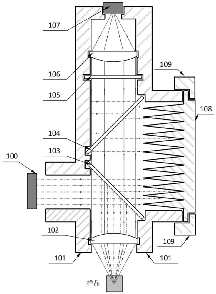
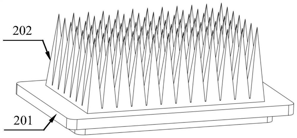
[0032] like figure 1 As shown, an extinction type weak fluorescence detection system in this embodiment includes: an excitation light optical path 100 , a light-shielding housing 101 , a fluorescence collecting lens 102 , a main dichroic mirror 103 , a secondary two A dichroic mirror 104, a bandpass filter 105, a converging lens 106, a photoelectric conversion detector 107, and a conical extinction filter 108;

[0033] The excitation light emitted by the excitation light path 100 is incident on the main dichroic mirror 103 in a parallel state, and then a part is reflected to the fluorescence collection lens 102, and then converged by the fluorescence collection lens 102 and then irradiated into the sample, and then incident on the main dichroic mirror. The other part of the excitation light on 103 passes through the main dichroic mirror 103 and then irradiates on the cone-surface light absorber 108, where it is dispersed and absorbed;

[0034] The fluorescence generated by th...

Embodiment 2

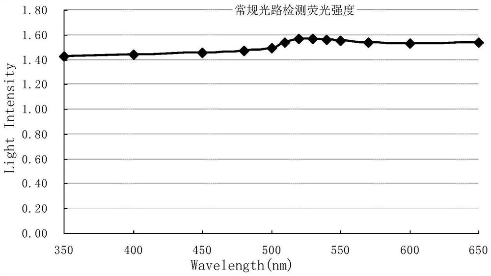
[0056] Compare the effects of Embodiment 1 of the present invention and the conventional fluorescence detection system, wherein, compared with Embodiment 1, the difference of the conventional fluorescence detection system is that there is no secondary dichroic mirror 104 and no conical surface quencher 108 therein.

[0057] The specific measurement method and process are as follows: before the detection, two sets of 13 interference narrow bandpasses with central wavelengths of 350nm, 400nm, 450nm, 480nm, 500nm, 510nm, 520nm, 530nm, 540nm, 550nm, 570nm, 600nm and 650nm are customized Filter, install narrow-band filters with different center wavelengths on the filter switching strip to form two sets of convenient and fast switching filter sets, which are respectively installed in the photoelectric conversion of the conventional fluorescence detection optical path and the fluorescence detection optical path of the present invention In front of the lens directly in front of the det...


PUM

PropertyMeasurementUnit
reflectanceaaaaaaaaaa

Abstract

The invention discloses an extinction type weak fluorescence detection system, comprising: an excitation light path, a light-shielding housing, a fluorescence collecting lens arranged in the light-shielding housing, a main dichroic mirror, a secondary dichroic mirror, a band-pass filter Light sheet, converging lens, photoelectric conversion detector, conical surface deluster. The present invention uses multiple dichroic mirrors in series to deeply filter the background excitation light entering the detection optical path, which can greatly reduce the energy ratio of the background excitation light in the target fluorescence, and can solve the problem that the fluorescence signal is easily excited by the background when the fluorescence signal is weak. The problem of light flooding; by setting the conical surface extinction device, the leaked incident excitation light can be efficiently absorbed, and the internal absorption surface of the detection optical path can be increased by using the slope method, and the light energy per unit area can be dispersed and reduced, thereby reducing the internally excited light. Interfering with fluorescence, increasing the turn-back times of leakage light absorption through the channel makes the extinction absorption more thorough, and then eliminates the fluorescence interference signal excited by the inner surface of the detection optical path, making the detection result more accurate.

Description

technical field [0001] The invention relates to the technical field of optical equipment, in particular to an extinction type weak fluorescence detection system. Background technique [0002] Fluorescence resonance energy transfer is an emerging molecular fluorescence detection technology that uses dipole interaction to transfer the energy of the donor excited state to the adjacent acceptor molecule. It has broad application prospects in biological macromolecular interaction, immunoassay, nucleic acid detection, etc. . Since the target fluorescence to be detected is not directly excited and converted by the excitation light, but the secondary fluorescence generated by the energy resonance transfer between the donor fluorescence and the adjacent acceptor, the fluorescence resonance energy transfer method generates the fluorescence resonance energy transfer method when the excitation light intensity is the same. The effective fluorescence intensity is much lower than the trad...

Claims


Application Information

Patent Timeline
Patent Type & Authority Patents(China)
IPC IPC(8): G01N21/64
CPCG01N21/645G01N2021/6463G01N2021/6471
Inventor 赵振英孙海旋王弼陡
Owner SUZHOU INST OF BIOMEDICAL ENG & TECH CHINESE ACADEMY OF SCI
Learn More