Auxiliary handle and electric tool

A technology of auxiliary handles and handles, which is applied in the field of auxiliary handles, can solve problems such as loose and complex structures, and achieve the effects of low manufacturing cost, simple structure, and high-efficiency adjustment effects

Pending Publication Date: 2020-12-22
JIANGSU DONGCHENG TOOLS TECH CO LTD
View PDF0 Cites 0 Cited by
  • Summary
  • Abstract
  • Description
  • Claims
  • Application Information

AI Technical Summary

Problems solved by technology

It can be seen that although the above-mentioned solutions all have a depth gauge limiter, this type of structure is loose and complicated.

Method used


Image

  • Auxiliary handle and electric tool
  • Auxiliary handle and electric tool
  • Auxiliary handle and electric tool

Examples


Embodiment Construction

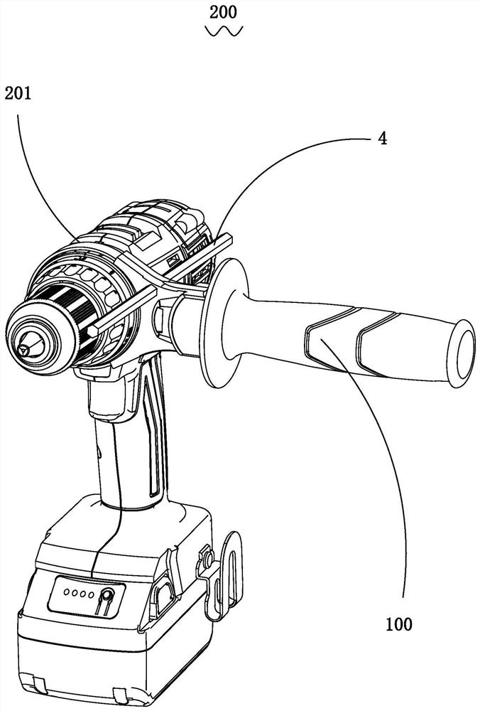
[0024] Such as Figure 1 to Figure 5 Shown is an auxiliary handle 100 related to a preferred embodiment of the present invention, which is applied to a power tool 200 such as a hammer drill. The electric tool 200 includes a tool body 201 with a working axis, the auxiliary handle 100 is fixedly connected to the front of the tool body 201 , and the auxiliary handle 100 is arranged along a direction perpendicular to the working axis.

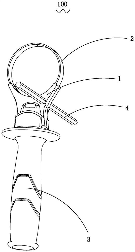
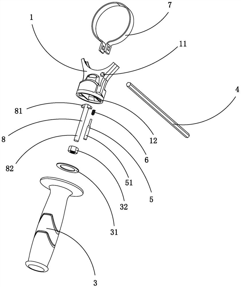
[0025] Such as figure 2 and 3 As shown, the auxiliary handle 100 includes a base body 1 , a clamp assembly 2 supported on the base body 1 , and a handle body 3 disposed at the bottom of the base body 1 , and the clamp assembly 2 is connected to the handle body 3 . The clamp assembly 2 includes a clamp 7 supported on the upper end of the seat body 1 and a fixing member 8 accommodated in the seat body 1, the upper end of the fixing member 8 is clamped on the lower end of the clamp 7, and the fixing member The lower end of 8 is fixed in the handle...


PUM


Abstract

The invention discloses an auxiliary handle. The auxiliary handle comprises a base body, a hoop assembly supported on the base body and a handle body arranged at the bottom of the base body, wherein the hoop assembly is connected to the handle body, the base body comprises an installation hole penetrating through the side face of the base body and a containing portion penetrating through the bottom face of the base body, the containing portion communicates with the installation hole and is adjacent to the top face of the handle body, the auxiliary handle comprises a depth gauge contained in the installation hole and a pressing pin contained in the containing portion, one end of the pressing pin abuts against the top face of the handle body, and the other end of the pressing pin abuts against the depth gauge. By means of the arrangement, the auxiliary handle can loosen the fixing mode of the depth gauge only through one rotating action, the adjusting effect of the depth gauge can be simply and efficiently achieved, and meanwhile, the auxiliary handle is simple in structure and low in manufacturing cost.

Description

[technical field] [0001] The invention relates to an auxiliary part of an electric tool, in particular to an auxiliary handle used on an electric tool. [Background technique] [0002] Currently, many hand-held electric tools are provided with an auxiliary handle for assisting in holding the electric tool when it is running. At the same time, in some occasions where the processing depth needs to be controlled, such as an electric hammer or electric drill, a depth limit device will be additionally provided on the electric tool. At present, the handle function of electric tools is mainly realized through auxiliary handles, clamps, clamp brackets and T-bolts, while the depth limit function is set on the auxiliary handles. There are mainly two ways: 1. Through an additional storage The mounting hole of the depth gauge and the spring lock connected to the mounting hole are realized; 2. The depth gauge is clamped by an independent bolt and nut combination outside. It can be seen ...

Claims


Application Information

Patent Timeline
Patent Type & Authority Applications(China)
IPC IPC(8): B25F5/02B25F5/00
CPCB25F5/003B25F5/02
Inventor 彭小湖
Owner JIANGSU DONGCHENG TOOLS TECH CO LTD
Why Eureka
Try Eureka