
Stainless steel section bar cutting device

A cutting device, stainless steel technology, applied in the direction of feeding device, positioning device, large fixed members, etc., can solve the problems of stainless steel profiles such as easy wear, inconvenient processing, concave corners, etc., to achieve the effect of improving safety and high practicability

Active Publication Date: 2020-12-22
张严艳
View PDF10 Cites 1 Cited by
  • Summary
  • Abstract
  • Description
  • Claims
  • Application Information

AI Technical Summary

Problems solved by technology

[0003] Most of the existing stainless steel profiles are cut by a cutting machine, and the cutting machine needs to manually feed the steel, and the stainless steel profiles after cutting usually fall into the lower receiving device, and the general cutting table is located at a higher position , the fallen stainless steel profiles are easy to wear or the corners are dented, which brings inconvenience to the later processing

Method used


Image

  • Stainless steel section bar cutting device
  • Stainless steel section bar cutting device
  • Stainless steel section bar cutting device

Examples


Embodiment

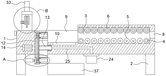
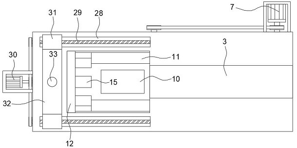
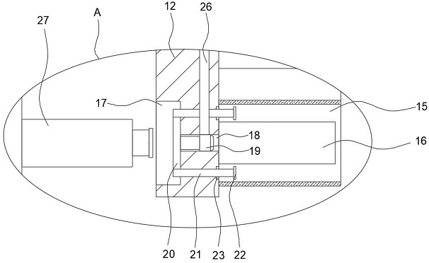
[0027] refer to Figure 1-5 , a stainless steel profile cutting device, comprising a processing table 1 and two support seats 2 fixedly installed on both sides of the lower end of the processing table 1, a conveying box 3 is embedded on the right side of the upper end of the processing table 1, and a conveying box 3 is provided inside the conveying box 3. device, the conveying device includes driving rollers 4 that are connected to the front and rear inner walls of the conveying box 3 and are respectively located at both ends of the lower interior of the conveying box 3, and play the role of conveying stainless steel profiles. There are a plurality of guide rollers 5, the guide rollers 5 are flush with the upper ends of the driving rollers 4, and play the role of supporting the stainless steel profile. The ends of the two driving rollers 4 on the rear side both penetrate the rear side wall of the conveying box 3 and extend to the processing table 1 At the rear, a first motor 7...


PUM


Abstract

The invention discloses a stainless steel section bar cutting device which comprises a processing table and two supporting bases fixedly mounted at the two sides of the lower end of the processing table, wherein a conveying box is embedded into the right side of the upper end of the processing table; a conveying device is arranged inside the conveying box; the conveying device comprises drive rollers which are rotatably connected to front and rear inner walls of the conveying box and are separately positioned at the two ends below the inner part of the conveying box; a plurality of guide rollers are uniformly arranged on positions, between the two drive rollers, in the conveying box; the guide rollers are flush to the upper ends of the drive rollers; ends, at the rear side, of the two drive rollers penetrate through the rear side wall of the conveying box and extend to positions behind the processing table; and a first motor is fixedly mounted at the rear end of the processing table. The stainless steel section bar cutting device has the advantages of high degree of automation, automatically regulating and cutting by the conveying device and an unloading device, greatly improving cutting efficiency, guaranteeing quality of stainless steel section bars and improving safety.

Description

technical field [0001] The invention relates to the technical field of cutting devices, in particular to a cutting device for stainless steel profiles. Background technique [0002] Stainless steel profiles are stainless steel materials obtained by hot-melting and extruding stainless steel rods to obtain different cross-sectional shapes. The cross-sectional shapes are roughly divided into stainless steel angle steel, flat steel and square steel with standard specifications. These stainless steel profiles have good mechanical strength. And toughness, so it is widely used in engineering construction, and when using these stainless steel profiles, they need to be cut to the required length. [0003] Most of the existing stainless steel profiles are cut by a cutting machine, and the cutting machine needs to manually feed the steel, and the stainless steel profiles after cutting usually fall into the lower receiving device, and the general cutting table is located at a higher pos...

Claims


Application Information

Patent Timeline
Patent Type & Authority Applications(China)
IPC IPC(8): B23Q7/00B23Q7/05B23Q5/26B23Q11/00B23Q3/08B23Q1/25
CPCB23Q7/00B23Q7/055B23Q5/26B23Q11/0067B23Q3/08B23Q1/25Y02P70/10
Inventor 张严艳
Owner 张严艳
Learn More