
Chemical soil treatment device

A soil and chemical technology, applied in the restoration of polluted soil, incinerators, grain treatment, etc., can solve problems such as equipment failure, neglect of soil debris treatment, etc.

Inactive Publication Date: 2020-12-22
卢超
View PDF0 Cites 1 Cited by
  • Summary
  • Abstract
  • Description
  • Claims
  • Application Information

AI Technical Summary

Problems solved by technology

[0004] However, in the prior art, the treatment of the sundries in the soil is often not paid attention to, and the polluted soil is often directly stirred with the remediation agent, so that the sundries interfere with the stirring rod, resulting in equipment failure

Method used


Image

  • Chemical soil treatment device
  • Chemical soil treatment device
  • Chemical soil treatment device

Examples


Embodiment 1

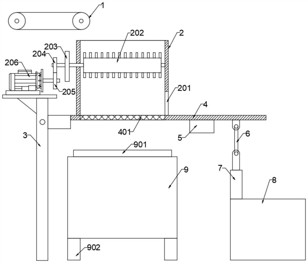
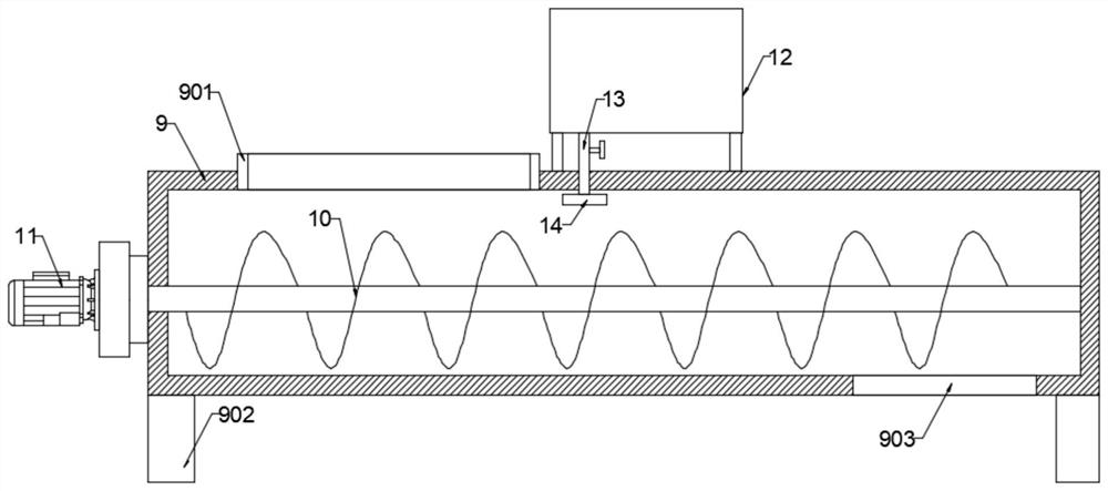
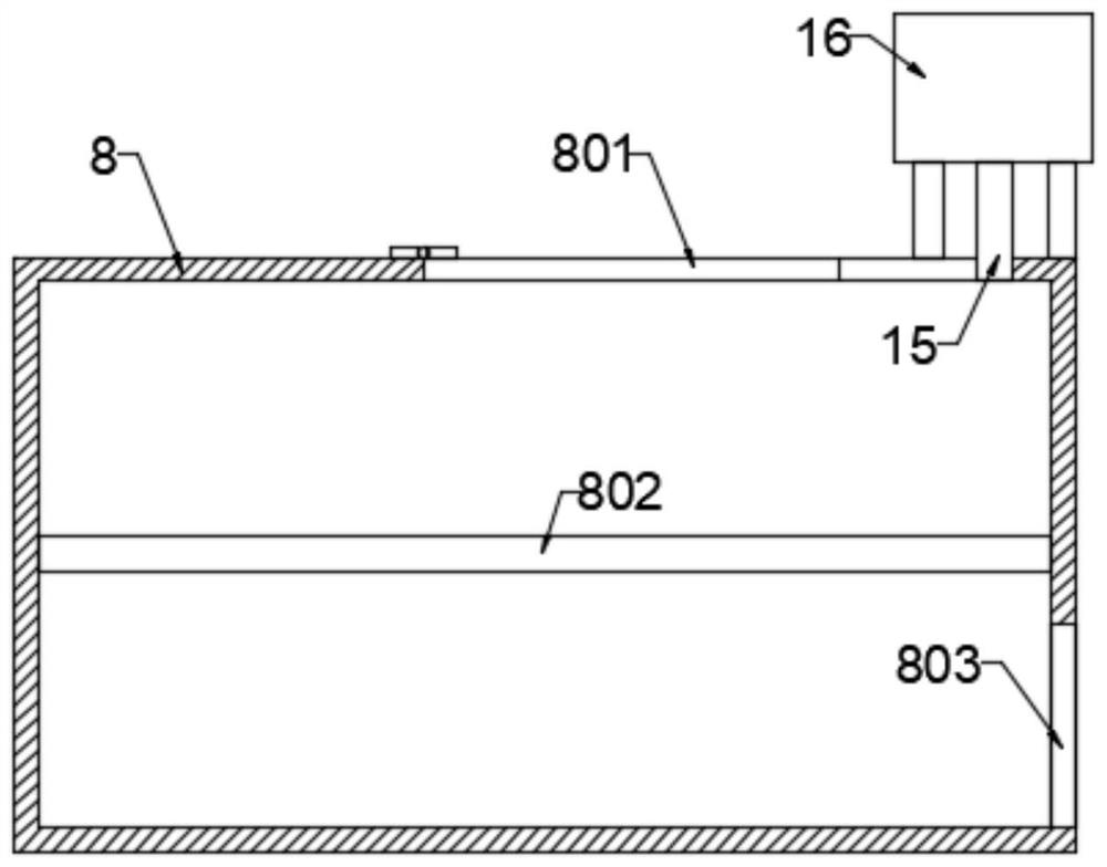
[0028] see Figure 1-5 , a chemical soil treatment device, comprising a feed mechanism 1, a support frame 3, a movable plate 4 installed on the support frame 3 and a sundry disposal box 8, the movable plate 4 is fixedly connected with a pretreatment box 2, the movable plate 4. The plate body located at the bottom of the cavity of the pretreatment box 2 is set as a first grid plate 401, and a soil remediation box 9 for repairing soil is arranged below the first grid plate 401. One end of the movable plate 4 is connected to the supporting frame 3 Rotationally connected, the other end of the movable plate 4 is hinged with a symmetrically distributed connecting rod 6, and the connecting rod 6 is hinged with the piston rod of the cylinder 7 installed on the sundry disposal box 8. mechanism, the movable plate 4 is fixedly connected with a vibrating motor 5 for vibrating the movable plate 4, and the side of the same direction of the pretreatment box 2 and the sundries disposal box 8 ...

Embodiment 2

[0033] This embodiment is expanded on the basis of Embodiment 1. The inner cavity of the flue gas treatment box 16 is fixedly connected with a partition plate 1601 that divides it into a first cavity 1602 and a second cavity 1603. The second cavity 1603 communicates with the smoke exhaust pipe 15. The flue gas treatment box 16 is provided with a flue gas treatment mechanism 17. The flue gas treatment mechanism 17 includes an activated carbon filter plate 1701, a cathode plate 1702 and an anode plate 1703. The activated carbon filter The plate 1701 is nested in the second cavity 1603 and is fixedly connected with the second handle 20 located outside the flue gas treatment box 16. There is an open box 1705 nested in the second cavity 1603 under the activated carbon filter plate 1701, and the opening The opening of the box 1705 faces the activated carbon filter plate 1701. One side of the opening box 1705 is fixedly connected with the third handle 21 located outside the flue gas t...


PUM


Abstract

The invention discloses a chemical soil treatment device which comprises a feeding mechanism, a supporting frame, a movable plate and a sundry treatment box, the movable plate and the sundry treatmentbox are installed on the supporting frame, the movable plate is fixedly connected with a pretreatment box, and a plate body, located at the bottom of a cavity of the pretreatment box, of the movableplate is a first grid plate. A soil remediation box used for remediating soil is arranged below the first grid plate, one end of the movable plate is rotationally connected with the supporting frame,symmetrically-distributed connecting rods are hinged to the other end of the movable plate, the connecting rods are hinged to an air cylinder piston rod installed on the sundry treatment box, and a crushing mechanism for splitting soil blocks is arranged in the pretreatment box. The movable plate is fixedly connected with a vibration motor used for vibrating the movable plate. According to the soil remediation device, soil can be rapidly remediated, garbage and impurities in the soil can be treated, smoke generated after incineration is harmlessly discharged, and secondary pollution is avoided.

Description

technical field [0001] The invention relates to a soil treatment device, in particular to a chemical soil treatment device. Background technique [0002] Soil remediation is a technical measure to restore the normal function of polluted soil. In the soil remediation industry, there are more than one hundred existing soil remediation technologies, and there are more than ten commonly used technologies, which can be roughly divided into three methods: physical, chemical and biological. Since the 1980s, many countries in the world, especially developed countries, have formulated and carried out plans for the treatment and restoration of contaminated soil, thus forming a new soil restoration industry. Soil is the final destination of various pollutants, and the accumulation of pollutants has become one of the main environmental problems. [0003] Soil remediation refers to the use of physical, chemical and biological methods to transfer, absorb, degrade and transform pollutant...

Claims


Application Information

Patent Timeline
Patent Type & Authority Applications(China)
IPC IPC(8): B09C1/08B02C4/08B02C4/42B02C23/10B07B1/28B07B1/42B08B15/04B01D53/04B03C3/017B03C3/41B03C3/47F23G7/14F23J15/02
CPCB01D53/04B02C4/08B02C4/42B02C23/10B03C3/017B03C3/41B03C3/47B07B1/28B07B1/42B08B15/04B09C1/08F23G7/14F23G2201/60F23G2201/80F23G2202/60F23G2209/24F23J15/025F23J2217/102F23J2219/30
Inventor 卢超
Owner 卢超
Learn More