Fixing device for laying wires and cables
A fixing device, wire and cable technology, applied in the direction of the suspension device of the cable, etc., can solve the problems of cumbersome operation of the wire and cable and the fixing device, and achieve the effect of fixing and stable
- Summary
- Abstract
- Description
- Claims
- Application Information
AI Technical Summary
Problems solved by technology
Method used
Image
Examples
Embodiment 1
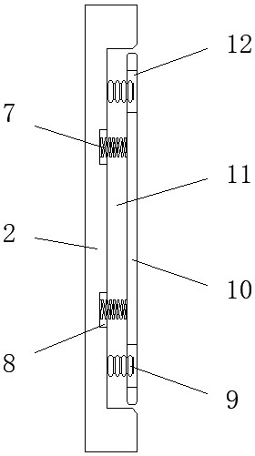
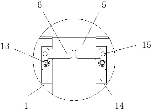
[0024] see figure 1 and image 3 , the present invention provides a technical solution: a fixing device for laying electric wires and cables, comprising a base 1, the front surface of the base 1 is provided with a slot 5, the inner wall of the slot 5 is provided with a bolt hole 4, the slot Both sides inner walls of 5 are provided with square groove 14, and the inside of square groove 14 is provided with limiting plate 6, and limiting plate 6 is fixedly connected with fixed shaft 15 with the inner inner wall of square groove 14, and the inner end bottom of limiting plate 6 is fixed Connected with a torsion spring 13, the other end of the torsion spring 13 is fixed on the inner wall of the square groove 14, the torsion spring 13 is installed inside the square groove 14, the limiting plate 6 is perpendicular to the square groove 14, and the outer end of the limiting plate 6 The surface is an arc-shaped structure, the outer end surfaces of the limit plates 6 on both sides of the...
Embodiment 2
[0026] see figure 1 , Figure 4 and Figure 5 , the present invention provides a technical solution: a fixing device for laying wires and cables, including a base 1, the front surface of the base 1 is provided with a slot 5, and both sides of the slot 5 are provided with a pedestal 3, The outer end angles of the pedestal 3 are arc-shaped structures, the inner surface of the pedestal 3 is provided with a fixing groove 18, the inner side of the draw groove 5 is fixedly connected with a fixing column 16 at the inner end of the fixing groove 18, and the end of the fixing column 16 part is fixed inside the fixed groove 18, the end face of the fixed column 16 is fixedly connected with the inner wall of the fixed groove 18 with an inner spring 19, and the cushion 3 shrinks inwardly during the installation and fixing process of the wire and cable and the base 1, and the cushion 3 Without affecting the normal installation of wires and cables, the pedestal 3 presses the wires and cabl...
Embodiment 3
[0028] see figure 1 , Figure 4 and Figure 5 , the present invention provides a technical solution: a fixing device for laying wires and cables, including a base 1, the front surface of the base 1 is provided with a slot 5, and both sides of the slot 5 are provided with a pedestal 3, The inner side surface of the pedestal 3 is provided with a fixing groove 18, and the inner side of the draw-in groove 5 is fixedly connected with a fixing column 16 at the inner end of the fixing groove 18, and the end of the fixing column 16 is fixed in the inside of the fixing groove 18, and the fixing column 16 is connected with the fixing groove 18. The grooves 18 are engaged with each other, the inner side of the seat 3 is fixedly connected with the inner wall of the slot 5 with an outer spring 17, and the outer spring 17 is fixed on the outside of the fixed column 16, and the seat 3 is installed and fixed on the wire and cable and the base 1 The compression spring shrinks inward, and the...
PUM
 Abstract
Description
Claims
Application Information
 - R&D
- Intellectual Property
- Life Sciences
- Materials
- Tech Scout
- Unparalleled Data Quality
- Higher Quality Content
- 60% Fewer Hallucinations
Browse by: Latest US Patents, China's latest patents, Technical Efficacy Thesaurus, Application Domain, Technology Topic, Popular Technical Reports.
© 2025 PatSnap. All rights reserved.Legal|Privacy policy|Modern Slavery Act Transparency Statement|Sitemap|About US| Contact US: help@patsnap.com


