
Combined double-layer switch cabinet and combination method thereof

A combination method and switchgear technology, applied in substation/switch layout details, substation/switchgear cooling/ventilation, electrical components, etc., can solve problems such as the troublesome disassembly of the separation layer and the non-adjustable space of the upper and lower layers of the double-layer switchgear. , to achieve the effect of increasing the space above, stabilizing the rise and fall, and reducing wear and tear

Active Publication Date: 2020-12-18
雷朋电气集团有限公司
View PDF7 Cites 0 Cited by
  • Summary
  • Abstract
  • Description
  • Claims
  • Application Information

AI Technical Summary

Problems solved by technology

[0004] The purpose of the present invention is to provide a combined double-layer switchgear and its combination method, which is used to solve the problem that the upper and lower layers of the existing double-layer switchgear cannot be adjusted. At the same time, the separation layer of the existing double-layer switchgear is fixed Welded on the inner wall of the cabinet, it is troublesome to disassemble the partition layer;

Method used


Image

  • Combined double-layer switch cabinet and combination method thereof
  • Combined double-layer switch cabinet and combination method thereof
  • Combined double-layer switch cabinet and combination method thereof

Examples


Embodiment Construction

[0035]The technical solutions of the present invention will be clearly and completely described below in conjunction with the embodiments. Apparently, the described embodiments are only some of the embodiments of the present invention, not all of them. Based on the embodiments of the present invention, all other embodiments obtained by persons of ordinary skill in the art without creative efforts fall within the protection scope of the present invention.

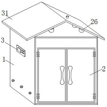
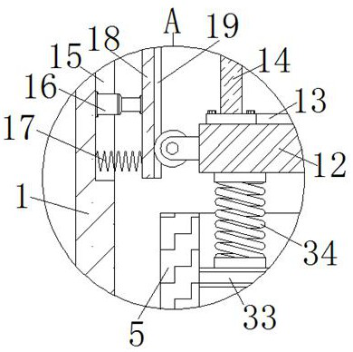
[0036] Such as Figure 1-6 As shown, a combined double-layer switch cabinet includes a main cabinet body 1, and two symmetrical cabinet doors 2 are arranged on the front of the main cabinet body 1, and the sides of the two cabinet doors 2 that are far away from each other are connected to the The front of the main cabinet body 1 is hinged, and the side of the main cabinet body 1 is provided with a PLC controller 3, and the PLC controller 3 is used to control the movement of the first electric push rod 8, the second electric ...


PUM


Abstract

The invention discloses a combined double-layer switch cabinet which comprises a main cabinet body, two symmetrical cabinet doors are arranged on the front face of the main cabinet body, a PLC is arranged on the side face of the main cabinet body, two symmetrical limiting blocks are fixedly installed on the inner bottom wall of the main cabinet body, an installation groove is movably connected between the close side faces of the two limiting blocks, first electric push rods are fixedly mounted on the inclined faces of the two mounting blocks correspondingly, an adjusting plate is fixedly mounted at the top of the sliding rail, a mounting frame is fixedly mounted at the top of the adjusting plate, and a fixing frame is fixedly mounted at the top of the mounting frame. A lifting adjusting plate of the adjusting plate can be controlled to ascend or descend, meanwhile, limiting rollers on the two sides are limited by the limiting plates, ascending and descending of the adjusting plate aremore stable, meanwhile, friction between the limiting rollers and the inner wall of the sliding groove is rolling friction, and abrasion between equipment parts is reduced.

Description

technical field [0001] The invention belongs to the field of electrical equipment and relates to switch cabinet technology, in particular to a combined double-layer switch cabinet and a combination method thereof. Background technique [0002] The switch cabinet is a kind of electrical equipment. The outside line of the switch cabinet first enters the main control switch in the cabinet, and then enters the sub-control switch. Each branch is set according to its needs, such as instruments, automatic control, motor magnetic switches, various AC contactors, etc. There is also a high-voltage room and a low-voltage room switchgear, and a high-voltage bus, such as a power plant. [0003] In the existing double-layer switchgear, the partition is generally arranged directly inside the cabinet, and the partition is fixed and welded between the inner walls of the cabinet, so as to divide the overall space of the cabinet into upper and lower spaces, but the position of the partition is...

Claims


Application Information

Patent Timeline
Patent Type & Authority Applications(China)
IPC IPC(8): H02B1/30H02B1/32H02B1/52H02B1/28H02B1/56
CPCH02B1/30H02B1/32H02B1/52H02B1/28H02B1/565
Inventor 武莎莎鲍朋乐倩云王紫欣张涛叶小婷鲁庆莫丽红
Owner 雷朋电气集团有限公司
Learn More