
Optical cable connection structure for human bionic signal monitoring and conversion system

A signal monitoring and conversion system technology, applied in the field of optical fiber transmission and connection, can solve problems such as equipment failure, large volume and space occupation, and complicated connection process

Active Publication Date: 2021-07-30
杭州克林曼科技有限公司
View PDF7 Cites 0 Cited by
  • Summary
  • Abstract
  • Description
  • Claims
  • Application Information

AI Technical Summary

Problems solved by technology

The existing connection method has the following disadvantages: 1. The socket is connected to the optical transceiver, and the plug is connected to the optical cable, which makes the connection process of the socket and the plug complicated, and the volume of the socket and the plug is large and takes up space; 2. The insertion of the socket and the plug increases. 3. The socket and plug are detachable. For non-equipment maintenance personnel, it is easy to disassemble and easily cause equipment failure and affect signal transmission.

Method used


Image

  • Optical cable connection structure for human bionic signal monitoring and conversion system
  • Optical cable connection structure for human bionic signal monitoring and conversion system
  • Optical cable connection structure for human bionic signal monitoring and conversion system

Examples


Embodiment Construction

[0032] Preferred embodiments of the present invention will be described in detail with reference to the accompanying drawings so that those embodiments can be easily realized by those having ordinary skill in the art to which the present invention pertains. However, the present invention can also be realized in various forms, so the present invention is not limited to the embodiments described hereinafter. In addition, in order to describe the present invention more clearly, parts not connected with the present invention will be omitted from the drawings.

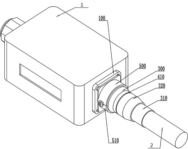
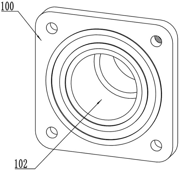
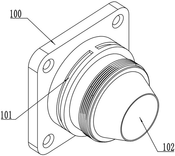
[0033] Such as Figure 1 to Figure 12 As shown, the optical cable connection structure for the human bionics signal monitoring and conversion system includes: optical terminal housing 1, layer twisted optical cable 2, connector 100, limiter 200, clamping member 210, fastening nut 220, outer sleeve A300 , rubber tube 310, outer sleeve B320, sealing ring A400, sealing ring B410, anti-disassembly part A500, anti-disassembly p...


PUM


Abstract

The invention relates to the field of optical cable connection, in particular to an optical cable connection structure for a human body bionics signal monitoring conversion system, which includes an optical terminal housing, a layered optical cable, a connecting piece, a limiting piece, a clamping piece, a fastening nut, and a jacket Tube A, rubber tube, outer casing B, sealing ring A, sealing ring B, anti-disassembly part A, anti-disassembly part B, the connecting parts are the installation section, the fixing section, the thread section, and the cone section from front to back , the cross-section of the mounting section of the connector is square, the cross-sections of the fixed section of the connector, the threaded section and the frustum of the cone are circular, the side length of the mounting section of the connector is greater than the diameter of the fixed section of the connector, and the diameter and length of the fixed section of the connector are greater than The cross-section diameter length of the threaded section of the connector; the present invention ensures that the optical fiber inside the stranded optical cable is not stressed by clamping the strengthening core, fiber layer and outer sheath of the stranded optical cable, and also satisfies the requirements of the stranded optical cable. tensile requirements.

Description

technical field [0001] The invention relates to the technical field of optical fiber transmission and connection, in particular to an optical cable connection structure for a human body bionics signal monitoring conversion system. Background technique [0002] The human bionics signal monitoring conversion system needs to convert the electrical signal collected from the human body into an optical signal through a high-speed signal processing circuit and an electro-optical conversion circuit for high-speed transmission, so that it can replace the cable transmission mode between the original connection device and the device communication network. The optical signal transmission based on the human bionics signal monitoring and conversion system between the interconnected devices is completed by using the optical cable. [0003] The connection between the existing layer-stranded optical cable and the optical transceiver is generally connected through a connector. The common conn...

Claims


Application Information

Patent Timeline
Patent Type & Authority Patents(China)
IPC IPC(8): G02B6/36
CPCG02B6/36G02B6/3628
Inventor 邵良
Owner 杭州克林曼科技有限公司
Learn More