A scissor handle dipping equipment
A technology of dipping and knife handle, which is applied to the device and coating of the surface coating liquid, which can solve the problems of troublesome operation, low work efficiency, and easy hand burns, etc., to achieve convenient operation, high work efficiency, and avoid burnt effect
- Summary
- Abstract
- Description
- Claims
- Application Information
AI Technical Summary
Problems solved by technology
Method used
Image

Examples
Embodiment 1
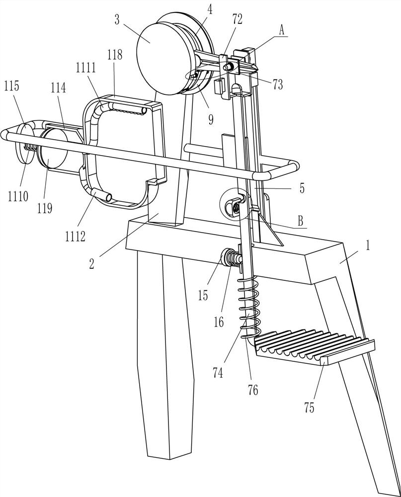
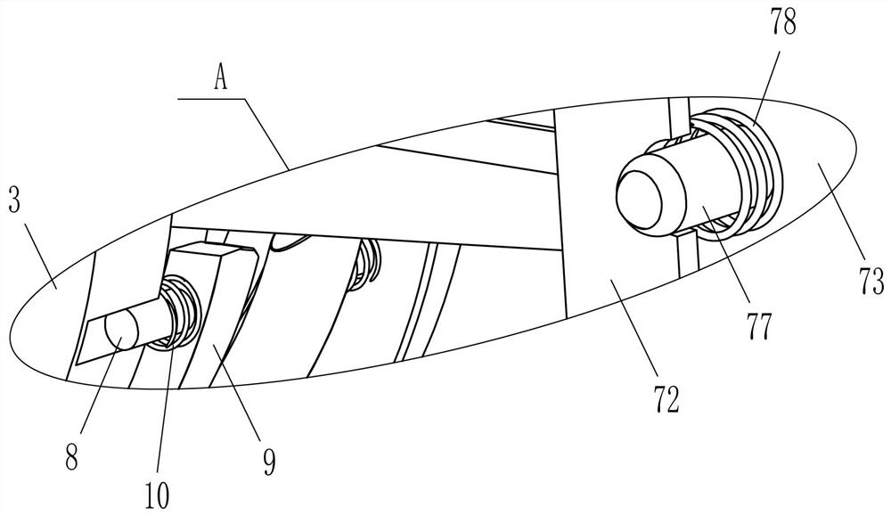
[0022] A scissor handle dipping equipment, such as Figure 1-Figure 3 As shown, it includes a base 1, a support plate 2, a circular frame 3, a heating wire 4, a riser 5, a clamping mechanism 7, a guide rod 8, an arc-shaped limit block 9 and a third spring 10, and the outer top of the base 1 A support plate 2 is affixed symmetrically to the front and back on the left side, and a circular frame 3 is affixed between the inner surfaces of the support plates 2 on the front and rear sides, and a circular frame 3 is affixed to the front and rear sides of the circular frame 3. Heating wires 4 are affixed to the circular frame 3 There are guide rods 8 evenly spaced at the bottom of the inner front and back sides, and arc-shaped stop blocks 9 are fixedly connected between the inner ends of the guide rods 8 on each side. The third spring 10 is connected between the inner front side of the 3, and the third spring 10 is also connected between the rear side of the rear side arc-shaped limit...
Embodiment 2
[0027] On the basis of Example 1, such as figure 1 with figure 2 As shown, it also includes a glue spraying mechanism 11, and the glue spraying mechanism 11 includes a fixed rod 111, a guide sleeve 112, a fourth spring 113, a cylinder body 114, a T-shaped bar 115, a return bar 116, a limit plate 117, a heating Housing 118, piston block 119, fifth spring 1110, glue spraying pipe 1111 and feeding pipe 1112, the back-type rod 116 is slidingly provided between the lower parts of the support plates 2 on the front and rear sides, and the lower part of the outer sides of the support plates 2 on the front and rear sides Both are fixedly connected with a fixed rod 111, and a sliding guide sleeve 112 is provided on the fixed rod 111. A fourth spring 113 is wound between the left side of the guide sleeve 112 and the left end of the fixed rod 111. Cylinder 114 is fixedly connected between them, and the sliding type in cylinder 114 is provided with piston block 119, and the sliding type ...
Embodiment 3
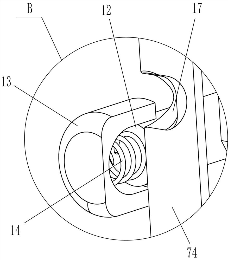
[0030] On the basis of embodiment 1 and embodiment 2, such as figure 1 , figure 2 with Figure 4 As shown, it also includes an L-shaped rod 12, a magnet cover 13 and a sixth spring 14. The front and rear sides of the outer top right side of the base 1 are fixedly connected with the L-shaped rod 12, and the inner end of the L-shaped rod 12 is slidably covered with a magnet. The sleeve 13 is connected with a sixth spring 14 between the inner surface of the magnet sleeve 13 and the inner end of the L-shaped rod 12 .
[0031] Also comprise limiting rod 15 and the 7th spring 16, movable rod 74 left side surface upper part has draw-in groove 17, and base 1 inner right side middle part sliding type is provided with limit rod 15, and limit rod 15 right-hand side and draw-in groove 17 Coordinated, a seventh spring 16 is wound between the inner left side of the limit rod 15 and the inner right side of the base 1 .
[0032] When an appropriate amount of colloid was sprayed on the han...
PUM
 Abstract
Description
Claims
Application Information
 - R&D
- Intellectual Property
- Life Sciences
- Materials
- Tech Scout
- Unparalleled Data Quality
- Higher Quality Content
- 60% Fewer Hallucinations
Browse by: Latest US Patents, China's latest patents, Technical Efficacy Thesaurus, Application Domain, Technology Topic, Popular Technical Reports.
© 2025 PatSnap. All rights reserved.Legal|Privacy policy|Modern Slavery Act Transparency Statement|Sitemap|About US| Contact US: help@patsnap.com