Eureka AIR delivers breakthrough ideas for toughest innovation challenges, trusted by R&D personnel around the world.

Magnetic auxiliary welding device and method

An auxiliary welding and connecting rib technology, applied in welding equipment, non-electric welding equipment, metal processing equipment, etc., can solve the problems of weakening the softening effect of the melting area, indentation of parts, and affecting the appearance quality of parts, etc., to increase the microhardness , Improve the effect of nugget shape

Active Publication Date: 2020-12-15
CRRC QINGDAO SIFANG CO LTD
View PDF5 Cites 5 Cited by
  • Summary
  • Abstract
  • Description
  • Claims
  • Application Information

AI Technical Summary

Problems solved by technology

For this reason, the present invention proposes a magnetic-assisted welding device, which is used to solve the defect that there are indentations in the appearance welding of the parts in the prior art, which affects the appearance quality of the parts. By arranging magnetic units around the electrodes, the workpiece to be welded In the process, a magnetic field that stirs the nugget is generated inside the workpiece to be welded, and the interaction between the magnetic field and the welding current performs three-dimensional and real-time regulation on the molten metal in the welding area, thereby increasing the microhardness of the internal structure of the nugget and improving the nugget. Shape, greatly weaken the softening effect of the melting zone in the axial direction and reduce indentation
[0006] The present invention also proposes a magnetic-assisted welding method, which is used to solve the indentation existing in the appearance welding of the parts in the prior art, which affects the appearance quality of the parts, realizes the reduction of the indentation on the surface of the workpiece to be welded, and improves the shape of the nugget

Method used


Image

  • Magnetic auxiliary welding device and method
  • Magnetic auxiliary welding device and method
  • Magnetic auxiliary welding device and method

Examples


Embodiment Construction

[0065] In order to make the purpose, technical solutions and advantages of the embodiments of the present invention clearer, the technical solutions in the embodiments of the present invention will be clearly and completely described below in conjunction with the drawings in the embodiments of the present invention. Obviously, the described embodiments It is a part of embodiments of the present invention, but not all embodiments. Based on the embodiments of the present invention, all other embodiments obtained by persons of ordinary skill in the art without making creative efforts belong to the protection scope of the present invention.

[0066] In the description of the embodiments of the present invention, it should be noted that the terms "center", "longitudinal", "transverse", "upper", "lower", "front", "rear", "left", "right" , "vertical", "horizontal", "top", "bottom", "inner", "outer" and other indicated orientations or positional relationships are based on the orientat...


PUM


Abstract

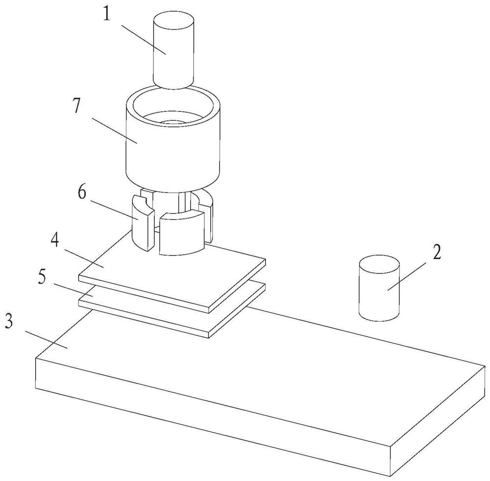
Embodiments of the invention provide a magnetic auxiliary welding device and method. The welding device comprises a first electrode, a second electrode, a substrate, a first to-be-welded workpiece, asecond to-be-welded workpiece and magnetic units, wherein the first to-be-welded workpiece and the second to-be-welded workpiece are arranged between the first electrode and the substrate in an overlapped mode; the second electrode and the second to-be-welded workpiece abut against the substrate; the magnetic units are annularly arranged on the outer side of the first electrode; the first electrode abuts against the surface of the first to-be-welded workpiece, and nuggets are formed between the first to-be-welded workpiece and the second to-be-welded workpiece; and the magnetic units are usedfor stirring the nuggets. According to the embodiments of the invention, the magnetic units are arranged around the electrodes, the stirring magnetic field for stirring the nuggets is generated in theto-be-welded workpieces, and the three-dimensional coincidence real-time regulation and control is carried out on the welding area under the interaction of the stirring magnetic field and the weldingcurrent, so that the microhardness of the internal structures of the nuggets is increased in mechanism, the nugget form is improved, and the softening effect of a melting area in the axial directionis weakened to reduce indentations.

Description

technical field [0001] The invention relates to the field of welding technology, in particular to a magnetic-assisted welding device and a welding method. Background technique [0002] Welding is an important process in the manufacture of rail vehicles, and resistance spot welding plays an important role in rail vehicle welding. The resistance spot welding process is the core joining process of thin-walled structures such as car bodies due to its advantages of high efficiency, low cost, and easy automation. However, resistance spot welding joints are prone to joint softening and local overheating, resulting in deep indentation and obvious burn marks, which seriously affect the surface quality of solder joints. For parts with high appearance requirements (such as unpainted stainless steel subway side walls, etc.), the common treatment method is to use single-sided resistance spot welding technology, supplemented by manual mechanical or chemical trace removal treatment after ...

Claims


Application Information

Patent Timeline
Patent Type & Authority Applications(China)
IPC IPC(8): B23K20/12B23K20/26
CPCB23K20/12B23K20/26
Inventor 韩晓辉徐野李刚卿叶结和刘勇
Owner CRRC QINGDAO SIFANG CO LTD
Why Eureka
Eureka Blog
Learn More