


Quick Research
Generate reliable direction feasibility study reports for your R&D in just a few steps.

Technical Q&A
Discover and master advanced knowledge NOW. Basics, ideas, possibilities, all at once.

Find Solutions
As an expert in R&D theories, this can generate solutions to your technical problems instantly.

Evaluate Feasibility
Analyze your overall solution with one click, know your potential R&D risks in advance.

Monitor Landscape
Get weekly tech updates, stay abreast of the latest tech innovations and key insights.
Centralized sand mixing device for cold core manufacturing and control method therefor
A technology of sand mixing and cold core, which is applied in the direction of cores, manufacturing tools, cleaning/processing machinery of casting materials, etc., can solve the problems of large space occupation, low maintenance cost, high maintenance cost, etc. The effect of low maintenance cost and simplified core-making structure
- Summary
- Abstract
- Description
- Claims
- Application Information
AI Technical Summary
Problems solved by technology
Method used
Image

Examples
Embodiment 1
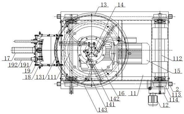
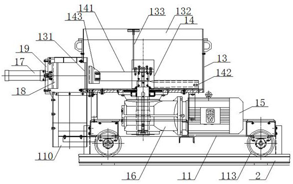
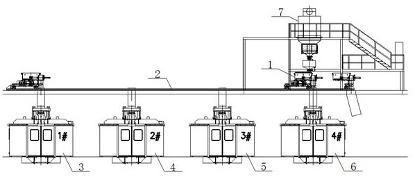
[0061] see figure 1 , figure 2 , a centralized sand mixing device for cold core core making, the centralized sand mixing device 1 includes a traveling mechanism, a stirring mechanism and a sand discharging mechanism, and the traveling mechanism includes a traveling trolley 11 and a device for driving the traveling trolley 11 to run along the track 2 Walking motor 12, front drive shaft 111 is installed on the front portion of described walking trolley 11, and rear transmission shaft 112 is installed on the rear portion of walking trolley 11, and the two ends of described front transmission shaft 111, rear transmission shaft 112 are all installed with The roller 113 that track 2 cooperates, described walking motor 12 is connected with rear transmission shaft 112 through gear box 114, and described mixing mechanism comprises mixing bucket 13, rotor 14 and driving device, and described mixing bucket 13 is installed on walking trolley 11 On the outer wall of the lower part of the...
Embodiment 2
[0082] Basic content is the same as embodiment 1, the difference is:
[0083] see figure 1 , figure 2 , the number of groups of the blades is three groups, and each group of blades includes arc-shaped blades 141 and straight blades 142 arranged sequentially from top to bottom, and the arc-shaped blades 141 are evenly arranged along the tangential direction of the outer wall of the rotor 14. The straight blades 142 are evenly arranged along the tangential direction of the outer wall of the rotor 14, and the straight blades 142 are arranged obliquely; the end of the arc-shaped blade 141 close to the inner wall of the mixing bucket 13 is connected with a scraper 143, and the scraper 143 includes a straight plate and a slanted plate. One end of described inclined plate is connected with straight plate, and straight plate is connected with the end of arc blade 141, and the other end of described inclined plate is provided with cutting surface; A riser 133 is vertically connected...
Embodiment 3
[0085] Basic content is the same as embodiment 1, the difference is:
[0086] see figure 1 , figure 2 , the cylinder 17 is installed on the bracket 19, the output end of the cylinder 17 is connected with the sand discharge door 18, the bracket 19 is connected with the mixing bucket 13, and the position on both sides of the cylinder 17 on the bracket 19 is equipped with linear bearings 191 , The linear bearing 191 is sleeved with a guide rod 192, and the guide rod 192 is connected with the sand discharge door 18.
PUM
 Abstract
Description
Claims
Application Information
 - R&D Engineer
- R&D Manager
- IP Professional
- Industry Leading Data Capabilities
- Powerful AI technology
- Patent DNA Extraction
Browse by: Latest US Patents, China's latest patents, Technical Efficacy Thesaurus, Application Domain, Technology Topic, Popular Technical Reports.
© 2024 PatSnap. All rights reserved.Legal|Privacy policy|Modern Slavery Act Transparency Statement|Sitemap|About US| Contact US: help@patsnap.com