
Wet dust removal type energy-saving coal-fired boiler

A technology for wet dust removal and coal-fired boilers, applied in the field of coal-fired boilers, can solve problems such as difficult disassembly

Inactive Publication Date: 2020-12-11
金丽颖
View PDF1 Cites 3 Cited by
  • Summary
  • Abstract
  • Description
  • Claims
  • Application Information

AI Technical Summary

Problems solved by technology

The invention not only realizes the heat recovery and purification treatment of the boiler tail gas, but more importantly, greatly improves the disassembly and assembly technology of the boiler induced draft fan, and can effectively solve the problem that the threaded assembly of the boiler induced draft fan is continuously and automatically locked under load and is not easy to disassemble , especially suitable for convenient disassembly of large boiler fans after thread locking; but this invention cannot automatically level the added coal

Method used


Image

  • Wet dust removal type energy-saving coal-fired boiler
  • Wet dust removal type energy-saving coal-fired boiler
  • Wet dust removal type energy-saving coal-fired boiler

Examples


specific Embodiment approach 1

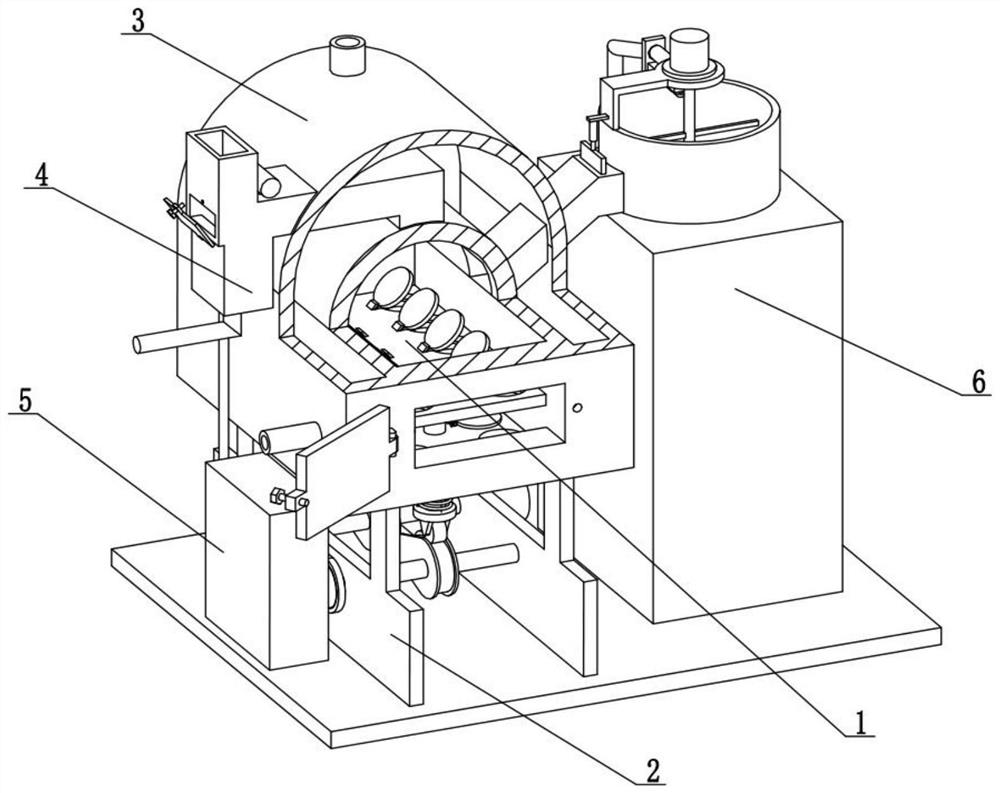
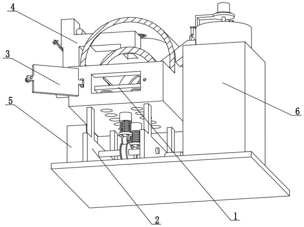
[0027] Combine below Figure 1-9 Describe this embodiment. The present invention relates to the technical field of coal-fired boilers, more specifically, a wet dust removal energy-saving coal-fired boiler, including a floating oxygen supply and leveling mechanism 1, a floating drive mechanism 2, a boiler body mechanism 3, and a dust removal chimney mechanism 4 , dust removal spray mechanism 5 and coal wet feeding mechanism 6, described dust removal spray mechanism 5 and coal wet feeding mechanism 6 are respectively fixedly connected to the left and right ends of the floating drive mechanism 2, and the boiler body mechanism 3 is fixedly connected to the floating drive mechanism 2 , the floating oxygen supply leveling mechanism 1 is slidingly connected in the boiler body mechanism 3, the coal wet feeding mechanism 6 is connected and communicated with the boiler body mechanism 3, the dust removal chimney mechanism 4 is connected and communicated with the boiler body mechanism 3, a...

specific Embodiment approach 2

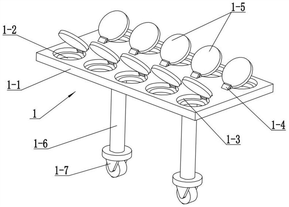
[0030] Combine below Figure 1-9Describe this embodiment, this embodiment will further explain the first embodiment, the floating oxygen supply leveling mechanism 1 includes a undulating plate 1-1, an air hole 1-2, an annular circular platform 1-3, an angle inclined plate 1-4, Cover 1-5, sliding rod 1-6 and contact wheel 1-7, two contact wheels 1-7 are respectively fixedly connected to the bottom of two sliding rods 1-6, and two sliding rods 1-6 are all fixedly connected to The bottom of the undulating plate 1-1, the undulating plate 1-1 is provided with a plurality of air holes 1-2, and the plurality of air holes 1-2 are all provided with an annular round table 1-3, and the plurality of shielding covers 1-5 are rotated respectively Connected to a plurality of annular round platforms 1-3, a plurality of angled inclined plates 1-4 are all arranged on the undulating plate 1-1, and a plurality of angled inclined plates 1-4 correspond to a plurality of shielding covers 1-5 respect...

specific Embodiment approach 3

[0033] Combine below Figure 1-9 Describe this embodiment, this embodiment will further explain the second embodiment, the floating drive mechanism 2 includes a bottom plate 2-1, a vertical vertical plate 2-2, a rotating shaft 2-3, a driving cam 2-4, a synchronous Sprocket 2-5 and driving motor 2-6, two vertical vertical plates 2-2 are all fixedly connected on the base plate 2-1, and two rotating shafts 2-3 are all rotationally connected to two vertical vertical plates 2- 2, two driving cams 2-4 are respectively fixedly connected to the middle of the two rotating shafts 2-3, and two synchronous sprockets 2-5 are respectively fixedly connected to the left ends of the two rotating shafts 2-3, and one of the rotating shafts 2-3 3 is fixedly connected on the output shaft of the drive motor 2-6, two synchronous sprockets 2-5 are driven by a chain, the drive motor 2-6 is fixedly connected on one of the vertical vertical plates 2-2, and the two contact wheels 1 -7 line contacts on t...


PUM


Abstract

The invention relates to the technical field of coal-fired boilers, in particular to a wet dust removal type energy-saving coal-fired boiler. Added coal can be automatically flattened. The coal-firedboiler comprises a floating oxygen supply leveling mechanism, a floating driving mechanism, a boiler body mechanism, a dust removal chimney mechanism, a dust removal spraying mechanism and a coal wetting and feeding mechanism; a rotating shaft and a driving cam on the rotating shaft are driven by a driving motor to rotate for driving two synchronous chain wheels to rotate synchronously; the otherdriving cam is driven by the other rotating shaft to rotate, so that two sliding rods and two contact wheels are driven by the the two driving cams to move up and down simultaneously; a fluctuating plate is driven by the two sliding rods to move up and down, and in the up-and-down moving process of the fluctuating plate, pulverized coal on the fluctuating plate can be driven to throw up and then fall down; and the pulverized coal falls onto the fluctuating plate, and is automatically laid flat, and the situation that the pulverized coal is concentrated and accumulated at a certain position, and consequently combustion is slow is avoided.

Description

technical field [0001] The invention relates to the technical field of coal-fired boilers, in particular to a wet-process dedusting energy-saving coal-fired boiler. Background technique [0002] The invention with the publication number CN105650659A discloses a cyclone wet dedusting energy-saving coal-fired boiler. The high-temperature tail gas pipe of the boiler body is connected to the induced draft fan through the water preheating tube heat exchanger and the cyclone dust collector; the sewage under the cyclone dust collector The water in the pool is connected to the spray plate in the cyclone dust collector through the spray pump; the high-level soft water pool is preheated by the shell side of the water preheating tube heat exchanger to supply water to the boiler; the pulley of the induced draft fan and the fan shaft and fan impeller Both the fan shaft and the fan shaft are assembled with self-locking threads; the fan impeller presses the copper-plastic reflexed composit...

Claims


Application Information

Patent Timeline
IPC IPC(8): F23B30/00F23J15/02F23K3/00F23L1/00B01D47/06
CPCB01D47/063F23B30/00F23J15/022F23K3/00F23K2203/008F23L1/00
Inventor 金丽颖
Owner 金丽颖
Learn More